
📘 CHAPTER OVERVIEW
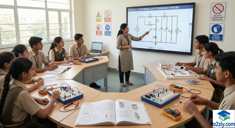
Work Education Class 9 introduces students to essential practical knowledge of electrical systems, safety devices, house wiring, motors, generators, electronic components, and measurement tools. This Work Education Class 9 Study Material 2025, created with guidance from a2zly.com, is designed according to NCERT + NEP 2025 competencies to help Class 9 students gain hands-on understanding, safety awareness, and real-life application skills.
The chapter progresses from basic safety devices to electromagnetism, motors & generators, switchboard connections, and modern electronics—ensuring students develop both conceptual understanding and practical competency through this comprehensive Work Education Class 9 Study Material 2025 offered by a2zly.com.
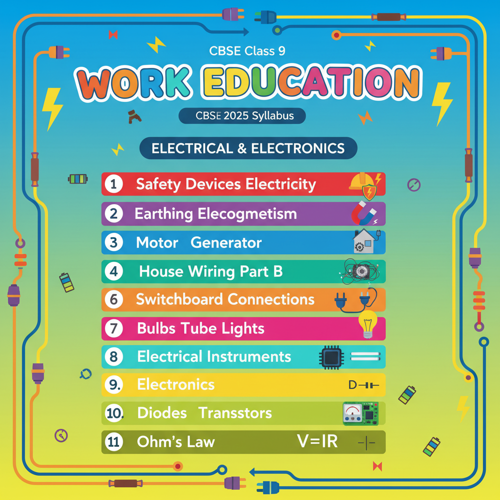
📚 Table of Contents
📚 DETAILED CONTENT OF Work Education Class 9 Study Material 2025
📘CHAPTER 1- Safety Devices in Electricity – Detailed Study Material
Safety devices are the foundation of electrical protection in Work Education Class 9. They prevent shocks, short circuits, overloads, and fire hazards, making electricity safer to use in homes and schools. This Work Education Class 9 Study Material 2025 briefly explains key safety devices like fuses, MCBs, ELCBs/RCCBs, isolators, and earthing so that Class 9 students can understand their purpose and real-life importance.
Below is the detailed explanation of the commonly used Fuse, MCB, ELCB/RCCB, and Isolators.
1. Fuse
🔹 Principle
A fuse works on the principle that:
A thin metal wire melts when too much current flows through it.
This happens because excess current makes the wire very hot, and at a certain point, the wire breaks (melts).
🔹 Use
A fuse protects:
- Household electrical appliances
- Wiring systems
- Electrical circuits
It prevents damage caused by:
- Overload (too many devices connected)
- Short circuit (sudden flow of very high current)
🔹 How a Fuse Works (Step-by-Step)
- Under normal current → fuse wire remains safe.
- If extra current flows (due to fault) → wire becomes hot.
- When temperature increases beyond limit → wire melts.
- The circuit is broken/open → flow of electricity stops.
- Appliances become safe from damage or fire.
🔹 Example
If the current rating of a fuse is 5A, and more than 5A flows, the fuse wire will melt to protect the circuit
2. Circuit Breakers
Circuit breakers are improved safety devices used in modern homes. Unlike fuses, they do not need replacement after a fault. They can be reset easily.
A. MCB (Miniature Circuit Breaker)
🔹 Function
An MCB protects the electrical circuit from:
- Overload
- Short circuits
It is commonly used in household distribution boards.
🔹 How MCB Works
- Under normal current → switch remains ON.
- When overload or short circuit occurs → MCB trips (switch automatically turns OFF).
- After fixing the problem → MCB can be reset by flipping the switch ON again.
🔹 Advantages of MCB
- No need to replace anything
- Faster and safer than a fuse
- Easy to reset
- More accurate in detecting faults
B. ELCB/RCCB (Earth Leakage Circuit Breaker)
🔹 Purpose
ELCB/RCCB is used mainly to protect humans from electrical shocks.
🔹 How It Works
ELCB/RCCB constantly compares the current in:
- Live wire (phase)
- Neutral wire
If there is any difference, it means some current is leaking to earth (possibly through a human body).
Example:
A person accidentally touches a live wire → current may pass through their body to the ground → this is leakage.
🔹 Action
Whenever leakage occurs → ELCB/RCCB trips immediately and cuts off the electricity.
This prevents:
- Electric shocks
- Electrical fires
- Damage to equipment
🔹 Important Points
3. Isolators
An isolator is a manual switch used to completely disconnect a part of the circuit for safety during maintenance or repair.
🔹 When Are Isolators Used?
- During repair of electrical equipment
- During maintenance of transmission or distribution systems
- To ensure complete safety of electricians/technicians
🔹 Important Feature
Unlike MCB or ELCB, an isolator does not trip automatically.
It must be operated manually.
🔹 Types of Isolators
There are mainly two types used in domestic and industrial supply:
📌 Summary Chart: Safety Devices
| Safety Device | Protects From | Working Principle | Automatic/Manual | Reusable? |
|---|---|---|---|---|
| Fuse | Overload, short circuit | Wire melts when current is high | Automatic (melts) | ❌ No (must replace) |
| MCB | Overload, short circuit | Switch trips automatically | Automatic | ✔ Yes (reset) |
| ELCB/RCCB | Electric shock, leakage | Detects current imbalance | Automatic | ✔ Yes |
| Isolator | Maintenance safety | Manual disconnection | Manual | ✔ Yes |
📘 Real-Life Example
- When too many appliances run on one socket → fuse/MCB trips → prevents fire.
- If a water heater has leakage current → RCCB trips → prevents electric shock.
- During repair of transformers or circuits → isolators used to disconnect power safely.
📘 CHAPTER 2- Earthing (Grounding) – Detailed Study Material
Earthing is one of the most important safety practices in Work Education Class 9, as it protects people and appliances from electric shock and voltage surges. This Work Education Class 9 Study Material 2025 helps Class 9 students understand how earthing provides a safe path for fault current to flow into the ground, keeping electrical systems stable and secure.
1. What Is Earthing?
Earthing means connecting the electrical system to the earth (ground) using a metal plate, rod, or pipe.
This provides a safe path for unwanted or extra current to flow into the ground.
2. Importance of Earthing
Earthing protects both people and electrical devices. Here’s why it is important:
🔹 1. Prevents Electric Shock
If a live wire accidentally touches the metal body of an appliance (like a refrigerator or washing machine), that metal becomes charged.
If you touch it, you may get a shock.
Earthing ensures:
- Extra current moves safely to the ground
- The appliance’s body remains safe to touch
- No shock reaches the user
🔹 2. Protects Appliances from Voltage Surge
Sometimes voltage suddenly increases due to:
- Lightning
- Short circuits
- Faulty electrical supply
Excess voltage can damage appliances.
Earthing helps by safely diverting this high voltage into the ground, preventing damage.
🔹 3. Helps Fault Current Reach the Ground Safely
In case of any electrical fault, the extra current (fault current):
- Flows through the earthing wire
- Reaches the earth
- Prevents overheating, fire, and accidents
This makes the entire electrical system safer.
3. Uses of Earthing
Earthing plays a major role in homes, schools, industries, and all buildings.
🔹 Provides a Low-Resistance Path
Earthing wire gives least resistance, so extra current prefers to flow through it rather than the human body.
🔹 Keeps Voltage Levels Stable
It helps maintain:
- Balanced voltage
- Smooth functioning of appliances
- Safety of the electrical network
This is especially important in places with sensitive equipment (computers, medical machines, etc.)
4. Types of Earthing
Several methods are used depending on the building and soil type.
Here are the three most commonly used types:
A. Plate Earthing
🔹 Description
A metal plate (usually copper or galvanized iron) is:
- Buried deep underground (about 2–3 meters)
- Surrounded by charcoal and salt to improve conductivity
🔹 Where It Is Used
- Large buildings
- Industries
- Electrical substations
🔹 Benefits
- Provides strong and stable earthing
- Good for heavy loads
B. Rod Earthing
🔹 Description
A long metal rod (usually steel or copper) is:
- Inserted vertically into the earth
- Driven deep with a hammer
🔹 Where It Is Used
- Rocky areas where digging pits is difficult
- Industrial and domestic systems
🔹 Benefits
- Easy to install
- Works well in deep soil
C. Pipe Earthing (Most Common in Homes)
🔹 Description
A GI (Galvanized Iron) pipe is used instead of a plate or rod.
The pipe:
- Has holes for moisture circulation
- Is buried vertically in the earth
🔹 Where It Is Used
- Household wiring
- Small buildings
- General domestic electrical systems
🔹 Benefits
- Very economical
- Most commonly used earthing method
- Effective for simple home wiring
5. Why Do We Need Earthing in Houses?
Earthing in homes is essential because:
✔ Washing machines, fridges, irons, and heaters have metal bodies
✔ Any fault can make the body live
✔ Without earthing, touching the appliance can cause a severe shock
✔ Earthing keeps the metal body at zero potential (safe level)
6. Real-Life Example
If a refrigerator develops a wiring fault:
- The body becomes charged
- Current flows through the earth wire
- RCCB/ELCB may trip
- The person using the fridge remains safe
This is possible only because of good earthing.
📌 Summary Table
| Feature | Description |
|---|---|
| Purpose of Earthing | Prevents shock, protects appliances, stabilizes voltage |
| Path Provided | Low-resistance route to ground |
| Plate Earthing | Metal plate buried in earth |
| Rod Earthing | Long rod driven into soil |
| Pipe Earthing | GI pipe used (common at homes) |
| Main Benefit | Safety and protection from electrical faults |
📘 CHAPTER 3- Electromagnetism – Detailed Study Material
Electromagnetism is a key scientific principle in Work Education Class 9, explaining how electricity and magnetism work together to create useful devices. This Work Education Class 9 Study Material 2025 introduces Class 9 students to magnetic fields, electromagnets, and their real-life applications, helping them understand how modern electrical systems operate.
Electromagnetism is the branch of physics that explains the relationship between electricity and magnetism.
Many devices around us—motors, generators, fans, speakers—work on the principles of electromagnetism.
In this chapter, you will learn two important ideas:
- Faraday’s Law of Electromagnetic Induction
- Fleming’s Left-Hand & Right-Hand Rules
Let’s understand them one by one in simple language.
1. Faraday’s Law of Electromagnetic Induction
🔹 What is Electromagnetic Induction?
Electromagnetic Induction means:
A voltage (EMF) is produced in a conductor when the magnetic field around it changes.
This voltage can then produce current if the conductor is part of a closed circuit.
🔹 Faraday’s Law (Simple Explanation)
Faraday discovered that:
“Whenever the magnetic field (flux) around a conductor changes, an EMF (voltage) is induced (produced) in the conductor.”
This change can happen by:
- Moving a magnet near a coil
- Moving a coil near a magnet
- Increasing or decreasing the magnetic field
- Rotating the coil inside a magnetic field
🔹 Example (Easy to Understand)
If you move a magnet towards a coil → voltage is produced.
If you move the magnet away from the coil → voltage is produced again.
If you stop moving the magnet → no voltage is produced.
Conclusion:
Voltage is induced only when the magnetic field changes.
🔹 Applications of Faraday’s Law
Faraday’s law is the working principle of many machines and devices:
- Generators (produce electricity)
- Transformers
- Induction cookers
- Electric guitar pickups
- Bicycle dynamo lights
2. Fleming’s Rules
Fleming created two hand rules to help us remember the direction of:
- Force
- Current
- Motion
- Magnetic field
Depending on which device we are studying—motor or generator—we use different rules.
⭐ A. Fleming’s Left-Hand Rule (For Motors)
Used for electric motors, where:
- Current flows through a conductor
- Magnetic field is applied
- A force (motion) is produced
This rule helps us find the direction of force (motion) on the conductor.
🖐 How to Apply Left-Hand Rule
Stretch your left hand with:
- Thumb
- First (index) finger
- Second (middle) finger
Keep them at right angles to each other.
Each finger represents:
| Finger | Represents |
|---|---|
| Thumb | Force / Motion |
| First Finger | Magnetic Field (B) |
| Second Finger | Current (I) |
💡 Simple Example
If current goes up and magnetic field goes into the page, the conductor moves in the direction shown by the thumb.
This is how fans, mixers, electric motors work.
⭐ B. Fleming’s Right-Hand Rule (For Generators)
Used for electric generators, where:
- A conductor moves
- It cuts through a magnetic field
- An induced current is produced
This rule helps us find the direction of induced current.
🖐 How to Apply Right-Hand Rule
Stretch your right hand the same way as left-hand rule.
Each finger represents:
| Finger | Represents |
|---|---|
| Thumb | Motion of conductor |
| First Finger | Magnetic Field |
| Second Finger | Induced Current |
💡 Simple Example
When a coil rotates inside a magnet in a generator, the direction of induced current is given by this rule.
This is how electricity is produced in:
- Power plants
- Hydroelectric dams
- Wind turbines
📘 Difference Between Left-Hand & Right-Hand Rule
| Feature | Left-Hand Rule | Right-Hand Rule |
|---|---|---|
| Used For | Motors | Generators |
| Purpose | Find direction of force/motion | Find direction of induced current |
| Current Present? | Yes, supply current already present | No, current produced by movement |
| Hand Used | Left hand | Right hand |
📌 Quick Summary
Faraday’s Law
✔ Voltage is produced when magnetic field around a coil changes.
✔ Used in generators, transformers, induction cookers.
Fleming’s Left-Hand Rule (Motor Rule)
✔ Thumb = Force
✔ First finger = Magnetic field
✔ Second finger = Current
Fleming’s Right-Hand Rule (Generator Rule)
✔ Thumb = Motion
✔ First finger = Magnetic field
✔ Second finger = Induced current
📘 CHAPTER 4- Motor and Generator – Detailed Study Material
Motors and generators are important machines studied in Work Education Class 9, showing how electrical energy can be converted into motion and how motion can be converted back into electricity. This Work Education Class 9 Study Material 2025 helps Class 9 students understand the basic working principles, differences, and real-life uses of motors and generators in everyday appliances and industries.
Electric motors and electric generators are two of the most important machines used in daily life.
Although they look similar in structure, their purposes are completely opposite:
- Motor: Electricity → Motion
- Generator: Motion → Electricity
Let’s understand them in detail.
1. Electric Motor
🔹 What Is an Electric Motor?
An electric motor is a device that converts electrical energy into mechanical energy (motion).
This motion is used to run fans, mixers, pumps, and many machines.
🔹 Principle of Motor
Electric motors work on the principle:
A current-carrying conductor placed in a magnetic field experiences a force.
This rule is explained by Fleming’s Left-Hand Rule.
🖐 Fleming’s Left-Hand Rule (Motor Rule)
- Thumb → Force (motion of the conductor)
- First Finger → Magnetic field direction
- Second Finger → Current direction
The direction of force tells us how the coil or conductor will move.
🔹 How Does an Electric Motor Work? (Simple Explanation)
- Electric current flows through the coil inside the motor.
- The coil is placed between the poles of a magnet.
- Magnetic field + current → produces a force.
- This force makes the coil rotate continuously.
- The rotating coil is connected to a shaft → which rotates the motor’s output.
This rotational motion can be used to run many appliances.
🔹 Types of Electric Motors
1. DC Motor
- Works on direct current (DC).
- Simple design.
- Used in toys, small machines, car wipers.
2. Induction Motor (AC Motor)
- Works on alternating current (AC).
- Very efficient and commonly used in homes.
- Used in fans, pumps, washing machines.
3. Synchronous Motor
- Rotates at a constant speed.
- Used in industries and clocks.
🔹 Uses of Electric Motors
Electric motors are everywhere. Common uses include:
- Fans
- Pumps and water motors
- Mixers and grinders
- Electric vehicles
- Drilling machines
- Machines in factories
- Washing machines
- Vacuum cleaners
Motors make modern life convenient by converting electricity into useful mechanical work.
2. Electric Generator
🔹 What Is an Electric Generator?
An electric generator is a device that converts mechanical energy into electrical energy.
It is the opposite of an electric motor.
🔹 Principle of Generator
Generators work on the principle of:
Electromagnetic induction
discovered by Faraday, which states:
When a coil moves in a magnetic field, an EMF is induced in it.
This induced EMF produces electric current.
Fleming’s Right-Hand Rule is used to determine the direction of this induced current.
🖐 Fleming’s Right-Hand Rule (Generator Rule)
- Thumb → Motion of conductor
- First Finger → Magnetic field direction
- Second Finger → Induced current direction
🔹 How Does a Generator Work? (Simple Explanation)
- A coil (armature) is rotated mechanically.
- The coil rotates inside a magnetic field.
- As it rotates, the magnetic flux around the coil continuously changes.
- This changing flux induces voltage in the coil (Faraday’s Law).
- The induced voltage produces current, which is supplied to homes and industries.
Mechanical energy can come from:
- Water turbines
- Steam turbines
- Wind turbines
- Engines
🔹 Types of Electric Generators
1. AC Generator (Alternator)
- Produces alternating current (AC).
- Used in power plants.
- Supplies electricity to homes and industries.
2. DC Generator
- Produces direct current (DC).
- Used in battery charging, welding, small power systems.
🔹 Uses of Electric Generators
Generators are used wherever electricity is needed.
- Power plants (hydro, thermal, nuclear)
- Windmills and dams
- Vehicles (car alternators)
- Industries
- Hospitals (backup power)
- Emergency power supply systems
- Construction sites
- Portable generators for homes
📌 Differences Between Motor and Generator
| Feature | Motor | Generator |
|---|---|---|
| Energy Conversion | Electrical → Mechanical | Mechanical → Electrical |
| Principle | Fleming’s Left-Hand Rule | Faraday’s Law + Right-Hand Rule |
| Input | Electricity | Mechanical motion |
| Output | Motion | Electricity |
| Uses | Fans, machines | Power supply, charging, backup |
📘 Quick Summary
Electric Motor
✔ Converts electrical energy into mechanical energy
✔ Uses Fleming’s left-hand rule
✔ Types: DC motor, induction motor, synchronous motor
✔ Uses: Fans, pumps, mixers, machines
Electric Generator
✔ Converts mechanical energy into electrical energy
✔ Works on electromagnetic induction
✔ Types: AC generator, DC generator
✔ Uses: Power plants, vehicles, industries, emergency power
📘 CHAPTER 5- House Wiring (Part B) – Detailed Study Material
House wiring is an essential topic in Work Education Class 9, helping students understand how electrical circuits are safely installed in homes. This Work Education Class 9 Study Material 2025 guides Class 9 students through wiring components, switchboard connections, circuit layouts, and safety practices needed for proper household electrical installation.
House wiring is designed to safely deliver electricity to appliances like fans, lights, TVs, and refrigerators.
Understanding phase, neutral, earth, and why the switch must always be on the phase wire is essential for electrical safety.
1. Basic Principle of Switchboard Connections
Every electrical device in a house—bulb, fan, TV, fridge—needs three main wires for safe and proper working:
🔹 A. Phase Wire (Live Wire)
- Also called line wire or hot wire.
- Carries the current from the power supply to the appliance.
- It has high voltage (usually 220–240 V in India).
- It is the most dangerous wire because touching it can cause a shock.
👉 Color Code (Commonly Used): Red / Brown / Yellow
🔹 B. Neutral Wire
- Completes the circuit by providing the return path for the current.
- Its potential is nearly zero volts.
- It is not as dangerous as phase wire, but still should not be touched carelessly.
👉 Color Code: Black / Blue
🔹 C. Earth Wire (Ground Wire)
- Provides a safety path for leakage or extra current.
- Prevents electric shock by sending fault current safely to the ground.
- Connected to the metal body of appliances.
👉 Color Code: Green
📌 Why Three Wires Are Needed?
| Wire Type | Purpose |
|---|---|
| Phase | Supplies current to the appliance |
| Neutral | Returns current to complete the circuit |
| Earth | Safety wire to prevent shock and protect appliances |
Without these three wires, electrical systems would be unsafe and may not work properly.
2. Why the Switch Is Always in the Phase Wire
This is one of the most important safety rules in house wiring.
🔹 What Happens When Switch Is on Phase Wire?
When you place a switch on the phase wire:
- Turning the switch OFF disconnects the live current from the appliance.
- The appliance becomes completely safe to touch.
- No current reaches the appliance.
👉 This is safe and correct wiring.
🔹 What If Switch Is Placed on the Neutral Wire? (Wrong wiring)
If the switch is mistakenly connected to neutral:
- Turning the switch OFF only breaks the neutral connection.
- The appliance still remains connected to phase.
- The outer body or internal parts may still carry live voltage.
- Touching the device may give a shock even when it appears to be OFF.
👉 This is dangerous and must be avoided.
📌 Simple Example
Imagine a bulb where:
- Neutral is connected to the switch (wrong)
- Phase is directly connected to the bulb
Even if the switch is OFF, the bulb holder still has live 240 V inside it.
Touching it can cause a serious electric shock.
3. Safe Switchboard Wiring – How It Works
🔹 Correct Method
Phase → Switch → Appliance → Neutral
- The switch breaks the phase supply.
- Appliance becomes dead (safe) when switch is OFF.
🔹 Incorrect Method
Neutral → Switch → Appliance ← Phase
- The switch cuts off only the neutral.
- Appliance still has live voltage.
- Danger of shock remains.
4. Uses of Earth Wire in Switchboards
Earth wire is connected to:
- The metallic body of appliances
- The third pin of plugs
- The earth terminal of sockets
Why earth wire is important?
✔ Prevents shock
✔ Discharges leakage current
✔ Protects electronics from damage
✔ Works with RCCB/ELCB to trip during leakage
5. Summary Table
| Feature | Description |
|---|---|
| Phase Wire | Carries live current, dangerous |
| Neutral Wire | Completes the circuit |
| Earth Wire | Safety path for fault current |
| Switch in Phase | Makes appliance safe when OFF |
| Switch in Neutral | Hazardous, appliance stays live |
6. Real-Life Examples
Example 1: Fan Switch
When the fan switch is OFF:
- Phase wire is broken → fan receives no current.
Example 2: House Plug Socket
Three holes represent:
- Phase
- Neutral
- Earth (largest hole)
Earth ensures safety for iron, geyser, fridge, etc.
Example 3: Bulb Holder Shock
If switch is on neutral, touching the bulb holder can cause shock even when switch is OFF.
📘 Quick Summary
- Appliances need phase, neutral, earth.
- Switch must always be connected in phase wire.
- Switch on phase = safe
- Switch on neutral = shock risk
- Earth wire = safety from leakage and faults
📘 CHAPTER 6- Types of Switchboard Connections – Detailed Study Material
Switchboard connections are an important part of electrical installation in Work Education Class 9, helping students understand how switches, sockets, and appliances are safely connected. This Work Education Class 9 Study Material 2025 explains different types of switchboard connections in a simple way so Class 9 students can learn their purpose, wiring method, and real-life applications.
There are different types of switchboard connections depending on how many loads (devices) and switches are used.
Let’s understand each type with clear explanations and real-life examples.
1. One Load – One Switch
🔹 Meaning
One switch controls one electrical load, such as:
- One bulb
- One fan
- One tube light
🔹 Working
The switch is connected in the phase wire going to the bulb.
When the switch is ON → bulb glows.
When the switch is OFF → bulb goes off.
🔹 Example
A normal room bulb controlled by a single switch.
2. Two Loads – Two Switches
🔹 Meaning
Two separate switches control two different loads.
Example loads:
- Bulb + fan
- Bulb + night lamp
- Two bulbs
🔹 Working
Each switch is wired in series with its respective load.
Example:
- Switch 1 → Bulb
- Switch 2 → Fan
Turning ON one switch does not affect the other device.
🔹 Common Usage
Kitchen, bedroom, drawing room.
3. One Load – Two Switches (Staircase Wiring)
🔹 Meaning
A single light (usually staircase light or hall light) can be controlled from two different places.
🔹 Why is it used?
- In staircases: One switch at the bottom, one at the top.
- In long corridors: Switches at both ends.
- In large bedrooms: One switch near the door, one near the bed.
🔹 Working
Uses two-way switches that change connection paths.
Either switch can turn the light ON or OFF, regardless of the other switch’s position.
🔹 Example
Turning the staircase light ON at the bottom and OFF at the top.
4. Two Loads – One Switch
🔹 Meaning
One switch controls two loads together.
🔹 Working
The phase wire splits into two wires after the switch, each going to a separate load.
When switch is ON → both loads operate simultaneously.
When switch is OFF → both turn OFF.
🔹 Example
- Two tube lights in a hall connected to one switch
- Two bulbs in a large room
- Bulb + exhaust fan in some bathrooms
🔹 Note
Useful when two lights are meant to run together.
5. Bed Switch
🔹 Meaning
A switch installed near the bed, allowing the user to control room lights without getting up.
🔹 Working
The bed switch is connected in parallel with the main switch (door switch) for the same light.
This allows:
- Light ON/OFF from the door
- Light ON/OFF from the bed
🔹 Uses
- Bedrooms
- Hospital wards
- Hotels
🔹 Advantage
Convenience and safety (especially at night).
6. Fuse in Switchboard
🔹 Why is a fuse used?
To protect:
- Wires
- Appliances
- Switchboard itself
🔹 Working
Fuse is always placed before the switch in the phase wire.
If there is:
- Overload
- Short circuit
→ The fuse wire melts and cuts off current, preventing fire or damage.
🔹 Important
Fuse protects the entire switchboard connected after it.
7. Tube Light Connection
A tube light requires additional components along with the switch.
🔹 Components
- Choke/Ballast – Provides high voltage initially to start the tube.
- Starter – Helps ionize the gas inside the tube.
- Tube – Produces light when gas inside it glows.
- Switch – Controls the connection.
🔹 Working (Simple Explanation)
- When switch is ON
- Current flows through choke and starter.
- The starter gives a flicker; choke produces a high starting voltage.
- Gas inside the tube ionizes (gets charged).
- Tube light starts glowing.
- Once glowing, the starter is bypassed and choke maintains a steady current.
🔹 Common Use
Homes, classrooms, offices, shops.
📘 Summary Table of All Switchboard Connections
| Type of Connection | Description |
|---|---|
| One Load – One Switch | One switch controls one bulb/fan |
| Two Loads – Two Switches | Each load has its own switch |
| One Load – Two Switches | Staircase wiring, control from two points |
| Two Loads – One Switch | Both loads operate together from one switch |
| Bed Switch | Light controlled from both door and bed |
| Fuse in Switchboard | Protects circuit from overload |
| Tube Light Connection | Includes choke, starter, tube, and switch |
📌 Real-Life Examples
- Staircase lights in apartment buildings → one load, two switches
- Hospital beds → bed switch
- Living rooms → two loads, two switches (fan + light)
- Kitchen → two loads, one switch (two bulbs together)
📘 CHAPTER 7- Bulbs & Tube Lights – Detailed Study Material
Bulbs and tube lights are common lighting devices studied in Work Education Class 9, helping students understand how electrical energy is converted into light. This Work Education Class 9 Study Material 2025 explains the working principles, components, and differences between bulbs and tube lights so Class 9 students can connect the concepts to real-life household lighting.
1. Basic Principle of Electric Lighting
Electrical energy is converted into light energy.
When electric current flows through a bulb or tube light, it produces:
- Light (useful)
- Heat (sometimes wasteful, depending on the type of bulb)
Different bulbs convert electricity into light with different levels of efficiency.
2. Types of Bulbs
There are many light sources used in households and industries. The main types are:
A. Incandescent Lamp (Old Type Bulb)
🔹 Description
- Contains a tungsten filament inside a glass bulb.
- When current flows → filament becomes hot → glows → produces light.
🔹 Features
- Very cheap
- Produces more heat than light
- Very energy-inefficient
- Short lifespan
🔹 Use
- Mostly replaced by LED and CFL bulbs today.
B. Halogen Lamp
🔹 Description
- Improved version of incandescent lamp.
- Filled with halogen gas (iodine or bromine).
- Filament burns brighter and hotter.
🔹 Features
- Brighter than incandescent
- Slightly better efficiency
- Produces a lot of heat
- Short lifespan
🔹 Use
- Car headlights
- Projector lamps
- Floodlights
C. CFL (Compact Fluorescent Lamp)
🔹 Description
- Uses a gas-filled tube with a coating of fluorescent material.
- When excited by electric current, it produces bright white light.
🔹 Features
- Consumes far less power than incandescent
- More energy efficient
- Longer life
- Contains mercury, so must be disposed safely
🔹 Use
- Houses
- Shops
- Offices
D. LED (Light Emitting Diode) – Most Efficient Bulb
🔹 Description
LEDs use semiconductor materials that emit light when current passes through them.
🔹 Features
- Most energy-efficient lighting technology
- Produces almost no heat
- Longest lifespan
- Very low electricity consumption
- Available in many shapes and colors
🔹 Use
- Homes
- Schools
- Offices
- Flashlights
- Streetlights
- Emergency lights
🔹 Why LEDs are the best?
✔ Save 80–90% electricity
✔ Very bright
✔ Very long-lasting
✔ Eco-friendly
3. Domestic & Industrial Bulbs
Different environments require different types of lighting.
A. Domestic Bulbs (Used in Homes)
Common Types:
- LED bulbs (best choice)
- CFL bulbs
- Standard incandescent bulbs (old and inefficient)
- Small LED panels
Features:
- Low wattage (5–20W for LEDs)
- Soft light for comfortable indoor use
B. Industrial Bulbs (High-Intensity Lighting)
Common Types:
- HID lamps (High-Intensity Discharge Lamps)
- Tube lights
- Halogen floodlights
- Metal halide lamps
Features:
- Provide very bright light
- Used in large spaces, factories, stadiums, workshops
- High wattage
4. Power-Saving Bulbs
Saving electricity is important. The best power-saving lighting systems are:
A. CFL (Compact Fluorescent Lamp)
- Uses less power than incandescent
- Good efficiency
- Long life
- Still used in many homes
B. LED (Best Power-Saving Option)
- Highest efficiency
- Lowest electricity consumption
- Longest life
- Environment friendly
Why choose LEDs?
- Save a lot of electricity
- Reduce electricity bills
- Produce less heat
- Are safer and long-lasting
5. Tube Lights
Tube lights are widely used in homes, schools, shops, and offices.
A. Construction of a Tube Light
A tube light consists of:
- Long glass tube filled with low-pressure gas (usually mercury vapor)
- Fluorescent coating inside the tube
- Filaments at both ends
- Starter
- Choke/Ballast
- Switch
B. Working of Tube Light (Simple Explanation)
- When the switch is ON, current flows through the starter and filaments.
- The starter flickers, helping the gas inside the tube ionize.
- The choke (ballast) generates a high voltage to start the tube.
- Once the gas inside the tube glows, the tube emits bright white light.
- The starter is bypassed, and the choke regulates the current.
C. Advantages of Tube Lights
- Bright and uniform light
- Suitable for large rooms
- Long life
- More efficient than old incandescent bulbs
📌 Summary Table: Types of Bulbs & Tube Lights
| Type | Efficiency | Heat Production | Lifespan | Uses |
|---|---|---|---|---|
| Incandescent | Very low | Very high | Short | Rarely used |
| Halogen | Low | Very high | Short | Headlights, floodlights |
| CFL | Medium | Low | Long | Homes, shops |
| LED | Highest | Very low | Longest | Homes, offices, streets |
| Tube Light | Medium | Low | Long | Homes, offices |
📘 Quick Summary
Bulbs
- Convert electrical energy → light energy
- LED is the most efficient
- CFL is also power-saving
- Incandescent and halogen are outdated
Tube Lights
- Use gas discharge + fluorescent coating
- Require starter + choke
- Provide bright and even light
📘 CHAPTER 8- Electrical Instruments – Detailed Study Material
Electrical instruments play a key role in Work Education Class 9, helping students measure voltage, current, resistance, and check the condition of circuits. This Work Education Class 9 Study Material 2025 introduces important tools like testers, ammeters, voltmeters, and multimeters so Class 9 students can understand their use, purpose, and importance in safe electrical work.
In electrical circuits, we often need to measure different quantities such as current, voltage, and resistance.
To measure these values accurately, we use specialized instruments.
The most commonly used instruments are:
- Ammeter – measures current
- Voltmeter – measures voltage
- Multimeter – measures many quantities (voltage, current, resistance, etc.)
Let’s study them in detail.
1. Ammeter
🔹 What is an Ammeter?
An ammeter is an electrical instrument used to measure electric current flowing through a circuit.
Unit of Current: Ampere (A)
🔹 Principle
An ammeter has very low resistance.
Why?
- Because it must allow the entire current to pass through it.
- If resistance were high, it would reduce current and give wrong readings.
🔹 How is an Ammeter Connected?
Ammeter is always connected in series with the load.
✔ Series connection ensures:
- All current flowing in the circuit passes through the ammeter.
- Measurement is accurate.
✘ Never connect an ammeter in parallel
Because the low resistance will cause large current to flow, damaging the instrument.
🔹 Types of Ammeters
1. Analog Ammeter
- Has a moving needle pointer.
- Works on electromagnetic deflection.
- Simple to use.
2. Digital Ammeter
- Displays current as numbers on a screen.
- More accurate and commonly used today.
🔹 Uses of Ammeter
- Measuring current in labs
- Testing appliances
- Checking battery charging current
- Used in vehicles, chargers, power supplies, etc.
2. Voltmeter
🔹 What is a Voltmeter?
A voltmeter measures the potential difference (voltage) between two points in a circuit.
Unit of Voltage: Volt (V)
🔹 Principle
A voltmeter has very high resistance.
Why?
- It should not allow any significant current to flow through it.
- If current flows through the voltmeter, it may affect the circuit and give incorrect readings.
🔹 How is a Voltmeter Connected?
A voltmeter is always connected in parallel with the component whose voltage is to be measured.
✔ Parallel connection ensures:
- Voltmeter reads the voltage across the device.
- It does not disturb the circuit.
✘ Never connect a voltmeter in series
It will block the current because of its high resistance.
🔹 Types of Voltmeters
1. Analog Voltmeter
- Has a needle pointer.
- Uses electromagnetic coil movement.
2. Digital Voltmeter
- Gives direct reading in numbers.
- Highly accurate, used in modern instruments.
🔹 Uses of Voltmeter
- Checking the voltage of batteries
- Measuring household supply voltage
- Testing circuits in labs
- Used in AC/DC power systems
3. Multimeter
🔹 What is a Multimeter?
A multimeter is a multi-purpose instrument that can measure:
- Voltage (AC/DC)
- Current
- Resistance
- Continuity
- Diode testing
It is also called a VOM (Volt-Ohm-Milliammeter).
🔹 Principle
Modern multimeters use electronic sensing circuits and microprocessors to measure different electrical quantities.
🔹 Types of Multimeters
1. Analog Multimeter
- Uses a moving needle
- Less accurate
- Mostly used in old setups
2. Digital Multimeter (DMM)
- Gives readings on a digital display
- Very accurate
- Has advanced features (auto-range, buzzer, continuity test)
🔹 How to Use a Multimeter?
A multimeter has multiple ports and a rotating selector knob.
You can measure:
- Voltage → connect in parallel
- Current → connect in series
- Resistance → across the component
- Continuity → check if a wire/path is complete (beeps)
🔹 Uses of Multimeter
- Used by electricians, technicians, and engineers
- Testing batteries
- Troubleshooting circuits
- Checking fuse continuity
- Measuring device output
📘 Summary Table of Instruments
| Instrument | Measures | Resistance | Connection | Types |
|---|---|---|---|---|
| Ammeter | Current | Very low | Series | Analog, Digital |
| Voltmeter | Voltage | Very high | Parallel | Analog, Digital |
| Multimeter | Voltage, current, resistance, continuity | Medium (varies) | Series/Parallel depending on use | Analog, Digital (DMM) |
📌 Key Points to Remember
✔ Ammeter → Low resistance → Series
✔ Voltmeter → High resistance → Parallel
✔ Multimeter → Measures many values (versatile tool)
📘 CHAPTER 9- Electronics – Detailed Study Material
Electronics is an important part of Work Education Class 9, helping students understand basic components like resistors, capacitors, LEDs, transistors, and their role in simple circuits. This Work Education Class 9 Study Material 2025 makes these concepts easy for Class 9 students by explaining how electronic components work and how they are used in everyday devices.
In this chapter, we will learn about:
- Soldering iron
- Basic electronic components
- Resistors
- Capacitors
- LED
1. Soldering Iron
🔹 What is a Soldering Iron?
A soldering iron is a hand tool used to join electronic components by melting solder.
It is widely used in electronics, electrical repair work, and PCB assembly.
🔹 Working Principle
A soldering iron works on the principle of resistance heating:
- Electric current flows through a resistive heating element.
- The element gets heated quickly.
- Heat is transferred to the metal tip.
- The tip melts the solder (a mixture of tin and lead or lead-free alloy).
- Melted solder creates a permanent electrical connection between components.
🔹 Types of Soldering Irons
1. Pencil Type (Basic Type)
- Lightweight
- Simple design
- Heats up slowly
- Used for school-level and small electronic projects
2. Gun Type
- Looks like a pistol
- Heats very quickly
- Used for repairing wires and larger components
3. Temperature-Controlled Soldering Iron
- Has temperature adjustment
- Prevents overheating
- Used in precision electronics, mobile repair, and professional labs
🔹 Uses of Soldering Iron
- Soldering components on PCB
- Repairing electronic gadgets
- Connecting wires
- Assembling circuits in robotics and DIY projects
- Fixing broken connections in computers, mobiles, toys, etc.
2. Basic Electronic Components
Every electronic device—from mobile phones to calculators—contains a combination of small components.
Let’s study the three most basic and essential ones.
A. Resistors
🔹 What is a Resistor?
A resistor is an electronic component that opposes or limits the flow of current.
🔹 Functions of Resistors
- Limit current in a circuit
- Reduce voltage (voltage drop)
- Protect LEDs and other components from high current
- Used in dividers, timers, and filters
🔹 Color Code
Resistors have colored bands printed on them that represent their value in ohms (Ω).
Students at higher classes learn to decode these colors.
Example colors:
- Black, Brown, Red, Orange, Yellow, Green, Blue, Violet, Grey, White
Each color corresponds to a number.
🔹 Types of Resistors
- Fixed resistors
- Variable resistors (potentiometers)
- Carbon film resistors
- Metal film resistors
🔹 Where Resistors Are Used?
- TVs, radios
- Mobile chargers
- LED circuits
- Computer motherboards
- Every electronic circuit
B. Capacitors
🔹 What is a Capacitor?
A capacitor is a device that stores electrical charge temporarily.
🔹 Functions of Capacitors
- Filtering in power supplies (removing noise)
- Smoothing voltage after rectification
- Timing circuits (along with resistors)
- Energy storage in flash cameras
- Blocking DC and allowing AC signals to pass
🔹 Types of Capacitors
- Ceramic capacitors (small, disk-shaped)
- Electrolytic capacitors (larger, polarized)
- Plastic/film capacitors
🔹 Important Note
Electrolytic capacitors have positive (+) and negative (-) terminals.
They must be connected correctly.
🔹 Uses of Capacitors
- Power supply circuits
- Fan regulators
- Mobile circuits
- Timer circuits
- Radio tuners
C. LED (Light Emitting Diode)
🔹 What is an LED?
An LED is a special diode that glows when electric current flows through it.
🔹 Features of LED
- Produces light with very little power
- Available in many colors (red, blue, green, white)
- Very long lasting
- Generates very little heat
🔹 How LED Works
- LED lights up when current flows from the anode (+) to cathode (–)
- LED requires a resistor in series to limit current
- If connected directly to a battery, it may burn out
🔹 Uses of LEDs
- Indicator lights on chargers, TVs, remotes
- Display boards
- LED bulbs
- Traffic signals
- Decorative lights
- Streetlights (high-power LEDs)
📘 Summary Table
| Component | Function | Connection/Principle | Examples of Use |
|---|---|---|---|
| Soldering Iron | Melts solder to join components | Resistance heating | PCB assembly, repairs |
| Resistor | Limits current, reduces voltage | Ohm’s Law, fixed value | LED circuits, dividers |
| Capacitor | Stores charge, filters voltage | Charge–discharge property | Power supplies, timing |
| LED | Produces light when current flows | Diode conduction | Indicators, displays |
📌 Quick Summary
✔ Soldering iron converts electricity into heat for joining components.
✔ Resistors limit current and help control voltage.
✔ Capacitors store charge and smooth signals.
✔ LEDs produce light with very little power.
📘 CHAPTER 10- Diodes & Transistors – Detailed Study Material
Diodes and transistors are key semiconductor components studied in Work Education Class 9, helping students understand how modern electronic devices control current flow and amplify signals. This Work Education Class 9 Study Material 2025 explains the working, types, and applications of diodes and transistors in a simple way so Class 9 students can connect these concepts to real-life electronics.
Electronics is built from small but powerful components.
Two of the most important components are:
- Diodes
- Transistors
These are used in almost every electronic device—mobiles, computers, chargers, TVs, radios, etc.
Let’s understand them in an easy way.
1. Diodes
🔹 What Is a Diode?
A diode is an electronic component that allows electric current to flow in only one direction.
It works like a one-way traffic gate for electricity.
🔹 Symbol of Diode
A triangle arrow pointing toward a line:
→|—
- Arrow side = Anode (+)
- Line side = Cathode (–)
🔹 How a Diode Works
A diode can work in two modes:
A. Forward Bias (ON State)
- Current flows from anode to cathode.
- Diode allows current to pass.
- Acts like a closed switch.
B. Reverse Bias (OFF State)
- Current does NOT flow.
- Diode blocks the flow.
- Acts like an open switch.
🔹 Functions / Uses of Diodes
Diodes are used for:
- Rectification (converting AC to DC)
- Protection of circuits
- Signal clipping
- Voltage regulation (Zener diode)
- Light emission (LED is a special diode)
Examples:
✔ Mobile chargers use rectifier diodes
✔ LED bulbs use LED diodes
✔ Power supplies use bridge rectifiers
2. Transistors
🔹 What Is a Transistor?
A transistor is a semiconductor device that can:
- Switch signals ON or OFF
- Amplify weak signals into stronger ones
It is called the heart of modern electronics.
🔹 Types of Transistors
There are two major families:
A. BJT (Bipolar Junction Transistor)
- Current-controlled device
- Small current at input → controls large current at output
B. FET (Field Effect Transistor)
- Voltage-controlled device
- Small voltage at input → controls current flow
🔹 Types of BJTs
BJTs have two main types:
1. NPN Transistor
- Most commonly used
- Current flows when base receives a small positive charge
2. PNP Transistor
- Opposite operation
- Current flows when base receives a small negative charge
🔹 Construction (Simple Idea)
A BJT has 3 terminals:
| Terminal | Function |
|---|---|
| Emitter | Emits charge carriers |
| Base | Controls current |
| Collector | Collects charge carriers |
A FET has:
| Terminal | Function |
|---|---|
| Gate | Controls voltage |
| Source | Input terminal |
| Drain | Output terminal |
🔹 Working Principle
BJT → Current-Controlled Device
- A small base current controls a much larger collector current.
- Used in amplifiers and switching circuits.
Example:
A small mic signal can control a loudspeaker sound → amplification.
FET → Voltage-Controlled Device
- A small voltage applied to the gate controls the current between drain and source.
- Uses very little power.
3. Uses of Transistors
Transistors are used in almost every modern electronic device.
A. As a Switch
Transistors can turn ON/OFF:
- LEDs
- Motors
- Buzzers
- Microcontrollers
B. As an Amplifier
Amplifies:
- Sound signals (microphones → speakers)
- Radio signals
- Sensor signals
C. As a Logic Device
Used in:
- Computers
- Mobile processors
- Digital circuits
📘 Summary Table
| Device | Controlled By | Direction of Current | Main Use |
|---|---|---|---|
| Diode | Fixed behavior | One direction only | Rectification, protection |
| BJT Transistor | Current | Both directions (depending on bias) | Switching, amplification |
| FET Transistor | Voltage | Controlled flow | Low-power switching |
📌 Quick Summary (For Exam)
- Diode = one-way device, forward & reverse bias.
- BJT = current-controlled transistor (NPN, PNP).
- FET = voltage-controlled transistor.
- Transistors used for switching & amplification.
📘 CHAPTER 11- Ohm’s Law – Detailed Study Material
Ohm’s Law is a fundamental concept in Work Education Class 9, explaining the relationship between voltage, current, and resistance in an electrical circuit. This Work Education Class 9 Study Material 2025 helps Class 9 students understand how the formula V=IRV = IRV=IR is used to calculate and analyze simple electrical circuits in real-life applications.
Electric circuits contain components like bulbs, resistors, motors, and wires.
To understand how voltage, current, and resistance are related in a circuit, we use a fundamental rule of electricity called Ohm’s Law.
This law is the foundation of electrical science and appears in almost every exam.
1. Statement of Ohm’s Law
Ohm’s Law states that:
Voltage (V) across a conductor is directly proportional to the current (I) flowing through it, provided the temperature remains constant.
In simple words:
- If voltage increases, current increases
- If voltage decreases, current decreases
- This relationship holds only when temperature does not change
2. Formula of Ohm’s Law
The mathematical form of Ohm’s Law is:
👉 V = I × R
Where:
- V = Voltage (Volt)
- I = Current (Ampere)
- R = Resistance (Ohm)
3. Meaning of Each Term
Voltage (V)
- Also called potential difference
- It is the “push” or pressure that makes current flow in a circuit
- Measured in Volts (V)
- Measured using a voltmeter
Current (I)
- Flow of electric charges (electrons)
- Measured in Amperes (A)
- Measured using an ammeter
Resistance (R)
- Opposition offered by a conductor to the flow of current
- Measured in Ohms (Ω)
- Depends on material, length, thickness, and temperature
Example:
- Thin wires have more resistance
- Thick wires have less resistance
4. Relationship Between V, I, and R
A. If voltage increases → current increases (if R is constant)
Example: A bulb will glow brighter if voltage increases.
B. If resistance increases → current decreases (if V is constant)
Example: A long thin wire allows less current.
C. If resistance decreases → current increases
Example: A thick copper wire carries more current.
5. Resistances in Circuits
A. Series Resistance
Total resistance increases:
Rₜ = R₁ + R₂ + R₃
Current remains the same in all components.
B. Parallel Resistance
Total resistance decreases:
1/Rₜ = 1/R₁ + 1/R₂ + 1/R₃
Voltage remains same across all components.
6. Practical Applications of Ohm’s Law
1. Designing circuits
Engineers use Ohm’s Law to calculate safe current for appliances.
2. Selecting resistors in electronics
To protect LEDs or transistors, we choose resistors using V = IR.
3. Household wiring
Helps determine wire thickness required to carry certain current.
4. Battery and charger design
Helps calculate how much current flows at a given voltage.
5. Electric heaters
Heating depends on resistance and current (P = I²R).
7. Simple Examples
Example 1
A current of 2 A flows through a resistor of 5 Ω.
Find voltage.
Using V = IR
V = 2 × 5 = 10 V
Example 2
Voltage = 12 V, Resistance = 6 Ω
Current?
I = V / R
I = 12 / 6 = 2 A
Example 3
Voltage = 9 V, Current = 3 A
Resistance?
R = V / I
R = 9 / 3 = 3 Ω
8. Important Conditions for Ohm’s Law
Ohm’s Law works only when:
✔ Temperature remains constant
✔ Material remains unchanged
✔ Current is not too high
✔ The conductor is “ohmic” (follows Ohm’s Law)
Devices like LEDs, diodes, transistors do NOT follow Ohm’s Law strictly.
9. Summary Table
| Quantity | Symbol | Unit | Measured By |
|---|---|---|---|
| Voltage | V | Volt (V) | Voltmeter |
| Current | I | Ampere (A) | Ammeter |
| Resistance | R | Ohm (Ω) | Ohmmeter / Multimeter |
📌 Quick Revision (Exam Points)
- Ohm’s Law: V ∝ I (Temperature constant)
- Formula: V = IR
- Voltage ↑ → Current ↑
- Resistance ↑ → Current ↓
- Used in designing circuits and choosing resistors
📚OBJECTIVE QUESTIONS
🔰 CHAPTER 1- 30 MCQs on Safety Devices (With Answers)
This set of MCQs is designed to help students of Work Education Class 9 revise all important safety devices such as fuses, MCBs, RCCBs/ELCBs, and isolators. These Work Education Class 9 Study Material 2025 questions strengthen understanding of how safety devices protect circuits from overload, short circuits, and electric shock, making them essential for Class 9 learners preparing for exams and practical applications.
1. What is the main purpose of a fuse in an electric circuit?
a) To increase current
b) To protect the circuit from overload
c) To store electricity
d) To measure voltage
Answer: b) To protect the circuit from overload
2. A fuse wire is made of a metal that has ________.
a) High melting point
b) Very low melting point
c) No melting point
d) High resistance to melting
Answer: b) Very low melting point
3. When excessive current flows through a fuse, it ________.
a) Expands
b) Melts and breaks the circuit
c) Allows more current
d) Starts glowing
Answer: b) Melts and breaks the circuit
4. Which safety device can be reused after a fault without replacement?
a) Fuse
b) MCB
c) Fuse carrier
d) Filament bulb
Answer: b) MCB
5. MCB stands for ________.
a) Maximum Current Breaker
b) Mini Current Blocker
c) Miniature Circuit Breaker
d) Minimum Circuit Breaker
Answer: c) Miniature Circuit Breaker
6. Which device protects mainly from electric shocks due to leakage?
a) MCB
b) Fuse
c) ELCB/RCCB
d) Transformer
Answer: c) ELCB/RCCB
7. ELCB/RCCB works by detecting ________.
a) Excessive heat
b) Current imbalance between live and neutral
c) Low voltage
d) Speed of current
Answer: b) Current imbalance between live and neutral
8. Which device must be operated manually?
a) MCB
b) RCCB
c) Isolator
d) Fuse
Answer: c) Isolator
9. A fuse protects appliances from ________.
a) Low voltage
b) Overheating due to overcurrent
c) Low current
d) Electric bill increase
Answer: b) Overheating due to overcurrent
10. In modern homes, fuses are mostly replaced by ________.
a) Batteries
b) MCBs
c) Motors
d) Transformers
Answer: b) MCBs
11. An isolator is used during ________.
a) Normal power supply
b) Maintenance or repair
c) Power generation
d) Rainy season
Answer: b) Maintenance or repair
12. MCB trips when ________.
a) Voltage increases
b) Current exceeds safe limit
c) Battery is low
d) Fan speed increases
Answer: b) Current exceeds safe limit
13. Fuse wire is generally made of ________.
a) Copper
b) Nichrome
c) Aluminium
d) Tin-lead alloy
Answer: d) Tin-lead alloy
14. In a three-phase system, which isolator is used?
a) One-pole
b) Two-pole
c) Four-pole
d) Five-pole
Answer: c) Four-pole
15. RCCB trips when leakage current is more than ________.
a) 0.1 mA
b) 10 mA
c) 30 mA
d) 1 A
Answer: c) 30 mA
16. Which device ensures complete disconnection from power lines for safety?
a) Switch
b) Isolator
c) Plug
d) Extension board
Answer: b) Isolator
17. The main drawback of a fuse is that it ________.
a) Cannot protect from fire
b) Needs replacement after melting
c) Works very slowly
d) Is very expensive
Answer: b) Needs replacement after melting
18. MCB is more preferred than a fuse because ________.
a) It is colorful
b) It can be reset easily
c) It works on batteries
d) It does not trip
Answer: b) It can be reset easily
19. Which device protects a person if they touch a live wire accidentally?
a) MCB
b) RCCB
c) Fuse
d) Overload relay
Answer: b) RCCB
20. A short circuit occurs when ________.
a) Voltage becomes very high
b) Two wires touch each other
c) Current becomes zero
d) Switch is off
Answer: b) Two wires touch each other
21. Which safety device is the most sensitive to leakage currents?
a) MCB
b) Fuse
c) RCCB
d) Switch
Answer: c) RCCB
22. The rating of a fuse is given in ________.
a) Volts
b) Ohms
c) Amperes
d) Hertz
Answer: c) Amperes
23. Which device automatically cuts off electricity during a fault?
a) MCB
b) Isolator
c) Socket
d) Bulb
Answer: a) MCB
24. RCCB ensures safety mainly in ________.
a) Lamps
b) Wet areas like bathroom/kitchen
c) Loudspeaker circuits
d) Street lights
Answer: b) Wet areas like bathroom/kitchen
25. A fuse should always be connected in the ________ wire.
a) Earth
b) Neutral
c) Live
d) Any wire
Answer: c) Live
26. When an MCB trips, the switch moves to ________.
a) Middle/off position
b) UP position
c) Down position forcibly
d) Moves randomly
Answer: a) Middle/off position
27. Which device is essential for working safely on electrical panels?
a) MCB
b) Isolator
c) Plug top
d) Meter
Answer: b) Isolator
28. RCCB stands for ________.
a) Residual Current Circuit Block
b) Residual Circuit Breaker
c) Residual Current Circuit Breaker
d) Required Current Breaker
Answer: c) Residual Current Circuit Breaker
29. The fuse wire must have ________.
a) High resistance
b) High melting point
c) Low melting point
d) High thickness
Answer: c) Low melting point
30. What happens if the current increases above the MCB rating?
a) MCB melts
b) MCB trips
c) Nothing happens
d) Devices get damaged
Answer: b) MCB trips
🔰 CHAPTER 2- 30 MCQs on Earthing (With Answers)
This collection of MCQs helps Work Education Class 9 students strengthen their understanding of earthing and its safety importance. These questions, aligned with Work Education Class 9 Study Material 2025, ensure Class 9 learners can confidently explain how earthing provides a safe path for fault current, prevents electric shock, and protects electrical appliances.
1. What is the main purpose of earthing?
a) To increase current flow
b) To prevent electric shock
c) To store electricity
d) To reduce resistance in wires
Answer: b) To prevent electric shock
2. Earthing provides a ________ path for extra current.
a) High-resistance
b) Low-resistance
c) Medium-resistance
d) No-resistance
Answer: b) Low-resistance
3. A fault current should flow directly into the ________.
a) Appliance
b) Transformer
c) Human body
d) Earth
Answer: d) Earth
4. Which of the following can be prevented by proper earthing?
a) Overheating
b) Electric shock
c) Voltage surge damage
d) All of these
Answer: d) All of these
5. Sudden voltage increase due to lightning is called a ________.
a) Short circuit
b) Voltage surge
c) Power drop
d) Current leak
Answer: b) Voltage surge
6. Earthing helps to keep the ________ stable in electrical systems.
a) Current
b) Voltage level
c) Resistance
d) Frequency
Answer: b) Voltage level
7. Which earthing type uses a metal plate buried underground?
a) Pipe earthing
b) Rod earthing
c) Plate earthing
d) Terminal earthing
Answer: c) Plate earthing
8. Plate earthing commonly uses plates made of ________.
a) Plastic
b) Rubber
c) Copper or galvanized iron
d) Wood
Answer: c) Copper or galvanized iron
9. Rod earthing uses a long metal rod inserted ________.
a) Horizontally
b) Angularly
c) Vertically
d) Randomly
Answer: c) Vertically
10. Which earthing method is MOST commonly used in households?
a) Plate earthing
b) Rod earthing
c) Pipe earthing
d) None of these
Answer: c) Pipe earthing
11. Pipe earthing usually uses a ________ pipe.
a) PVC
b) GI (Galvanized Iron)
c) Bamboo
d) Steel-plastic
Answer: b) GI (Galvanized Iron)
12. What do holes in the GI pipe help in?
a) Passing air
b) Moisture circulation
c) Storing water
d) Cooling the pipe
Answer: b) Moisture circulation
13. In which area is rod earthing mostly used?
a) Desert areas
b) Rocky areas
c) Wetlands
d) Snowy regions
Answer: b) Rocky areas
14. What happens if the metal body of an appliance becomes live?
a) Appliance turns off
b) Risk of electric shock
c) Appliance becomes safer
d) Voltage becomes zero
Answer: b) Risk of electric shock
15. Earthing keeps the metal body of an appliance at ________.
a) High potential
b) Zero potential
c) Medium potential
d) Negative potential
Answer: b) Zero potential
16. Which device works best along with earthing to prevent shock?
a) Fuse
b) RCCB / ELCB
c) Switch
d) Socket
Answer: b) RCCB / ELCB
17. Earthing is especially important in areas like ________.
a) Bedrooms
b) Dry storage rooms
c) Bathrooms and kitchens
d) Classrooms
Answer: c) Bathrooms and kitchens
18. What is the main function of charcoal and salt around the earthing plate?
a) Decoration
b) Improve conductivity
c) Increase resistance
d) Reduce soil moisture
Answer: b) Improve conductivity
19. When fault current flows to earth, the electrical system becomes ________.
a) Unstable
b) Safer
c) Faster
d) More expensive
Answer: b) Safer
20. Pipe earthing is preferred in homes because it is ________.
a) Cheapest and effective
b) Hard to install
c) Only for industries
d) Not long-lasting
Answer: a) Cheapest and effective
21. Which type of earthing is best for large buildings and industries?
a) Pipe earthing
b) Plate earthing
c) Rod earthing
d) No earthing needed
Answer: b) Plate earthing
22. The purpose of earthing is to send ________ into the ground.
a) Safe current
b) Excess or fault current
c) Normal current
d) No current
Answer: b) Excess or fault current
23. Earthing prevents the ________ of appliances.
a) Overuse
b) Overheating
c) Damage from high voltage
d) Mechanical wear
Answer: c) Damage from high voltage
24. Why is earthing important for sensitive devices like computers?
a) They use more electricity
b) They heat up easily
c) They need stable voltage
d) They are heavy
Answer: c) They need stable voltage
25. Without earthing, a fault current may flow through the ________.
a) Air
b) Human body
c) Ground directly
d) Ceiling
Answer: b) Human body
26. What happens if earthing is not done properly?
a) Appliances work faster
b) Risk of shock increases
c) Electricity bill reduces
d) Wires become stronger
Answer: b) Risk of shock increases
27. The term “grounding” is another name for ________.
a) Wiring
b) Earthing
c) Insulating
d) Charging
Answer: b) Earthing
28. Earthing ensures the electrical system remains ________.
a) Expensive
b) Complicated
c) Stable
d) Decorative
Answer: c) Stable
29. When a refrigerator has a fault, earthing helps current flow ________.
a) Into the human body
b) Into the earth
c) Back to the meter
d) Into the switchboard
Answer: b) Into the earth
30. Earthing is an important safety measure in ________.
a) Only industries
b) Only schools
c) Almost all buildings
d) Only factories
Answer: c) Almost all buildings
🔰 CHAPTER 3- 30 MCQs on Electromagnetism (With Answers)
This set of MCQs helps Work Education Class 9 students revise key concepts of electromagnetism, including magnetic fields, electromagnets, and their applications. Prepared as part of the Work Education Class 9 Study Material 2025, these questions strengthen Class 9 learners’ understanding of how electricity and magnetism work together in real-life devices.
1. Electromagnetism deals with the relationship between ________.
a) Heat and light
b) Electricity and magnetism
c) Sound and waves
d) Pressure and volume
Answer: b) Electricity and magnetism
2. Faraday’s Law states that an EMF is produced when ________.
a) Current is constant
b) Magnetic field around a conductor changes
c) Temperature increases
d) Voltage is high
Answer: b) Magnetic field around a conductor changes
3. The voltage produced due to changing magnetic field is called ________.
a) Resistance
b) Induced EMF
c) Heat energy
d) Static charge
Answer: b) Induced EMF
4. Which of the following can create electromagnetic induction?
a) Moving a magnet near a coil
b) Keeping a magnet still
c) Keeping a coil still
d) Heating the coil
Answer: a) Moving a magnet near a coil
5. Electricity generation in power plants works on ________.
a) Ohm’s Law
b) Faraday’s Law
c) Coulomb’s Law
d) Archimedes’ Principle
Answer: b) Faraday’s Law
6. In a generator, electricity is produced when a coil ________ inside a magnetic field.
a) Burns
b) Rotates
c) Breaks
d) Shrinks
Answer: b) Rotates
7. Fleming’s Left-Hand Rule is used for ________.
a) Generators
b) Motors
c) Batteries
d) Solar panels
Answer: b) Motors
8. Fleming’s Right-Hand Rule is used for ________.
a) Motors
b) Transformers
c) Generators
d) Switches
Answer: c) Generators
9. In Fleming’s Left-Hand Rule, the thumb represents ________.
a) Current
b) Magnetic field
c) Force or motion
d) Voltage
Answer: c) Force or motion
10. In Fleming’s Right-Hand Rule, the second finger represents ________.
a) Heat
b) Induced current
c) Force
d) Voltage
Answer: b) Induced current
11. The first finger in both Fleming’s rules represents ________.
a) Magnetic field
b) Force
c) Current
d) Resistance
Answer: a) Magnetic field
12. A motor converts ________ into ________.
a) Electricity → Motion
b) Motion → Electricity
c) Heat → Electricity
d) Light → Motion
Answer: a) Electricity → Motion
13. A generator converts ________ into ________.
a) Electricity → Motion
b) Motion → Electricity
c) Sound → Motion
d) Light → Electricity
Answer: b) Motion → Electricity
14. Which device works on Fleming’s Left-Hand Rule?
a) Fan motor
b) Generator
c) Transformer
d) Electric bell
Answer: a) Fan motor
15. Which device works on Fleming’s Right-Hand Rule?
a) Electric motor
b) DC fan
c) Generator
d) Battery charger
Answer: c) Generator
16. What is needed for electromagnetic induction to occur?
a) Constant magnet
b) Changing magnetic field
c) Constant current
d) High temperature
Answer: b) Changing magnetic field
17. If a magnet is moved faster near a coil, the induced EMF will be ________.
a) Zero
b) Smaller
c) Larger
d) Negative
Answer: c) Larger
18. A transformer works on the principle of ________.
a) Mechanical force
b) Electromagnetic induction
c) Heat transfer
d) Chemical reaction
Answer: b) Electromagnetic induction
19. Which of the following must move to induce current?
a) Magnet only
b) Coil only
c) Either magnet or coil
d) Both must be still
Answer: c) Either magnet or coil
20. In an electric motor, current flows through a coil placed in a ________.
a) Vacuum
b) Magnetic field
c) Water bath
d) Plastic tube
Answer: b) Magnetic field
21. The force produced in a motor is due to interaction between ________.
a) Heat and coil
b) Magnetic field and current
c) Charge and light
d) Resistance and power
Answer: b) Magnetic field and current
22. In Fleming’s Left-Hand Rule, the second finger shows the direction of ________.
a) Force
b) Current
c) Magnetic field
d) Induced EMF
Answer: b) Current
23. “Motion, Field, Current” order is represented by which rule?
a) Left-Hand Rule
b) Newton’s Law
c) Right-Hand Rule
d) Ampere’s Law
Answer: c) Right-Hand Rule
24. When a conductor cuts magnetic field lines, it develops ________.
a) Heat
b) EMF
c) Pressure
d) Sound
Answer: b) EMF
25. The part of a generator that rotates is called the ________.
a) Magnet
b) Rotor
c) Core
d) Terminal
Answer: b) Rotor
26. Which of the following devices DOES NOT work on electromagnetic induction?
a) Generator
b) Transformer
c) Electric motor
d) Solar panel
Answer: d) Solar panel
27. A stronger magnet in a generator will produce ________.
a) More EMF
b) Less EMF
c) No EMF
d) Noise only
Answer: a) More EMF
28. The direction of induced current changes when the ________ changes.
a) Color of magnet
b) Speed of motion
c) Direction of motion
d) Shape of coil
Answer: c) Direction of motion
29. In motors, force acts on a current-carrying conductor placed in a ________.
a) Magnetic field
b) Vacuum
c) Glass tube
d) Neutral zone
Answer: a) Magnetic field
30. Faraday’s Law is mainly used to explain the working of ________.
a) Heating coil
b) Light bulb
c) Generator
d) Solar heater
Answer: c) Generator
🔰 CHAPTER 4- 30 MCQs on Motor & Generator (With Answers)
This MCQ set helps Work Education Class 9 students revise the working principles of motors and generators, focusing on energy conversion and real-life applications. As part of the Work Education Class 9 Study Material 2025, these questions support Class 9 learners in understanding how electrical energy is turned into motion and how mechanical energy is converted back into electricity.
1. An electric motor converts ________ into ________.
a) Mechanical → Electrical
b) Electrical → Mechanical
c) Heat → Light
d) Mechanical → Heat
Answer: b) Electrical → Mechanical
2. An electric generator converts ________ into ________.
a) Mechanical → Electrical
b) Electrical → Mechanical
c) Heat → Electricity
d) Light → Motion
Answer: a) Mechanical → Electrical
3. Fleming’s Left-Hand Rule is used for ________.
a) Generators
b) Transformers
c) Motors
d) Batteries
Answer: c) Motors
4. Fleming’s Right-Hand Rule is used for ________.
a) Solar panels
b) Motors
c) Generators
d) Heaters
Answer: c) Generators
5. In a motor, the thumb in Fleming’s left-hand rule represents ________.
a) Magnetic field
b) Current
c) Force/Motion
d) Temperature
Answer: c) Force/Motion
6. In a generator, the second finger in the right-hand rule shows ________.
a) Force direction
b) Magnetic field
c) Induced current
d) Voltage
Answer: c) Induced current
7. What principle does a generator work on?
a) Ohm’s Law
b) Electromagnetic Induction
c) Heat Transfer
d) Newton’s Law
Answer: b) Electromagnetic Induction
8. A motor works because a current-carrying conductor in a magnetic field experiences ________.
a) Pressure
b) Force
c) Temperature change
d) Rotation of earth
Answer: b) Force
9. Which of the following is a type of motor?
a) DC motor
b) Alternator
c) Transformer
d) Battery
Answer: a) DC motor
10. Which of the following is a type of generator?
a) Induction motor
b) Synchronous motor
c) AC generator
d) BLDC motor
Answer: c) AC generator
11. DC motors run on ________.
a) AC supply
b) DC supply
c) Solar energy only
d) No electrical supply
Answer: b) DC supply
12. Induction motors run on ________.
a) AC supply
b) DC supply
c) No supply
d) Solar power only
Answer: a) AC supply
13. Which type of motor is used in ceiling fans?
a) DC motor
b) Induction motor
c) Synchronous motor
d) Hydraulic motor
Answer: b) Induction motor
14. Which type of generator is used in power plants?
a) DC generator
b) AC generator (alternator)
c) Battery generator
d) Solar generator
Answer: b) AC generator (alternator)
15. Which energy source is used to rotate a generator’s coil?
a) Mechanical energy
b) Electrical energy
c) Heat only
d) Light energy
Answer: a) Mechanical energy
16. Which device provides emergency backup electricity?
a) Motor
b) Generator
c) Bulb
d) Transistor
Answer: b) Generator
17. The rotating part of a generator is called ________.
a) Coil
b) Switch
c) Rotor
d) Armature
Answer: c) Rotor
18. In motors, current + magnetic field produce ________.
a) Heat
b) Sound
c) Force
d) Pressure
Answer: c) Force
19. Which machine is found in fans, mixers, and water pumps?
a) Generator
b) Electric motor
c) Transformer
d) Battery
Answer: b) Electric motor
20. Which rule helps find the direction of induced current?
a) Left-hand rule
b) Right-hand rule
c) Ohm’s rule
d) Maxwell’s rule
Answer: b) Right-hand rule
21. A motor shaft rotates because ________.
a) Wires melt
b) Force acts on the coil
c) Voltage drops
d) Air pushes it
Answer: b) Force acts on the coil
22. Which of the following is NOT a type of motor?
a) DC motor
b) Induction motor
c) Synchronous motor
d) AC generator
Answer: d) AC generator
23. In a generator, which factor induces EMF?
a) Constant magnetic field
b) Changing magnetic field
c) No magnetic field
d) Heating of the coil
Answer: b) Changing magnetic field
24. Alternators produce ________.
a) Alternating current (AC)
b) Direct current (DC)
c) No current
d) Only heat
Answer: a) Alternating current (AC)
25. DC generators produce ________.
a) AC
b) DC
c) No electricity
d) Flickering current
Answer: b) DC
26. Which device in vehicles produces electricity to charge the battery?
a) Motor
b) Alternator
c) Light
d) Pump
Answer: b) Alternator
27. A generator needs ________ to start producing electricity.
a) Light
b) Motion
c) Water only
d) Heat only
Answer: b) Motion
28. Motors are used in: (Choose the correct option)
a) Fans
b) Mixers
c) Drilling machines
d) All of the above
Answer: d) All of the above
29. Generators are widely used in ________.
a) Power plants
b) Emergency power supply
c) Industries
d) All of the above
Answer: d) All of the above
30. Which statement is TRUE about motors and generators?
a) Both convert electrical energy to heat
b) Motor and generator work on opposite principles
c) Both produce mechanical motion
d) Both use chemical reactions
Answer: b) Motor and generator work on opposite principles
🔰 CHAPTER 5- 30 MCQs on House Wiring (With Answers)
This set of MCQs helps Work Education Class 9 students revise important concepts of house wiring, including circuit layouts, switches, sockets, and safety practices. Prepared as part of the Work Education Class 9 Study Material 2025, these questions ensure Class 9 learners understand how household electrical systems are designed and safely operated.
1. How many main wires are needed for safe house wiring?
a) One
b) Two
c) Three
d) Four
Answer: c) Three
2. The phase wire is also known as the ________ wire.
a) Earth
b) Neutral
c) Live
d) Return
Answer: c) Live
3. The neutral wire usually carries ________.
a) High voltage
b) Zero or very low voltage
c) No current ever
d) Only AC
Answer: b) Zero or very low voltage
4. Which wire is the most dangerous to touch?
a) Neutral
b) Earth
c) Phase
d) All equally dangerous
Answer: c) Phase
5. The earth wire is usually ________ in color.
a) Red
b) Blue
c) Green
d) Yellow
Answer: c) Green
6. Why do we need an earth wire?
a) To increase voltage
b) To provide a safe path for fault current
c) To reduce electricity bill
d) To cool appliances
Answer: b) To provide a safe path for fault current
7. The switch must always be connected in the ________ wire.
a) Neutral
b) Earth
c) Phase
d) Any wire
Answer: c) Phase
8. If the switch is placed on the neutral wire, the appliance becomes ________.
a) Safe
b) Faster
c) Still live and dangerous
d) Grounded
Answer: c) Still live and dangerous
9. When a switch is OFF in phase connection, the appliance receives ________.
a) Full current
b) Half current
c) No current
d) Double current
Answer: c) No current
10. A bulb holder may give a shock even when OFF if the switch is connected to ________.
a) Neutral
b) Earth
c) Phase
d) Metal body
Answer: a) Neutral
11. Which wire completes the circuit by returning current?
a) Earth
b) Phase
c) Neutral
d) Live
Answer: c) Neutral
12. The largest pin in a 3-pin plug is for the ________.
a) Phase
b) Neutral
c) Earth
d) Switch
Answer: c) Earth
13. Earth wire protects appliances from ________.
a) Rust
b) Current leakage
c) Dust
d) Overheating
Answer: b) Current leakage
14. In correct wiring, the switch is connected between ________.
a) Neutral and earth
b) Phase and appliance
c) Phase and neutral
d) Earth and appliance
Answer: b) Phase and appliance
15. Which wire is connected to the metal body of appliances for safety?
a) Phase
b) Neutral
c) Earth
d) Plastic wire
Answer: c) Earth
16. Touching a neutral wire is usually safer because it is at ________.
a) High potential
b) Zero potential
c) Negative potential
d) Fluctuating potential
Answer: b) Zero potential
17. The earth wire prevents ________.
a) Electric shock
b) Water leakage
c) Light flickering
d) High temperature
Answer: a) Electric shock
18. When phase touches the metal body of an appliance, the current goes to ________.
a) Appliance
b) Ground through earth wire
c) Neutral directly
d) Switch
Answer: b) Ground through earth wire
19. Which wire brings electricity from power supply to the device?
a) Earth
b) Phase
c) Neutral
d) None
Answer: b) Phase
20. Which wire is used only for safety and not for normal current flow?
a) Phase
b) Neutral
c) Earth
d) Live
Answer: c) Earth
21. The color of phase wire is usually ________.
a) Green
b) Black
c) Red/Brown/Yellow
d) White
Answer: c) Red/Brown/Yellow
22. If the switch is in the neutral, the appliance is still connected to ________.
a) Earth
b) Phase
c) Both wires
d) Battery
Answer: b) Phase
23. Good house wiring prevents ________.
a) Accidents
b) Power loss
c) Fire hazards
d) All of these
Answer: d) All of these
24. Switchboards in homes control appliances by breaking the ________.
a) Earth circuit
b) Neutral circuit
c) Phase circuit
d) Ground circuit
Answer: c) Phase circuit
25. A 3-pin plug provides connection for ________.
a) Phase only
b) Phase and neutral
c) Phase, neutral, earth
d) Neutral and earth only
Answer: c) Phase, neutral, earth
26. Earth wire keeps the appliance body at ________.
a) 240 V
b) Zero potential
c) High potential
d) Negative potential
Answer: b) Zero potential
27. A properly earthed appliance reduces chances of ________.
a) Loose wires
b) Electric shock
c) High speed
d) Breakage
Answer: b) Electric shock
28. In India, household supply voltage is usually ________.
a) 50 V
b) 110 V
c) 220–240 V
d) 500 V
Answer: c) 220–240 V
29. If a fault occurs, earth wire directs current to ________.
a) Switch
b) Lamp
c) Ground
d) Air
Answer: c) Ground
30. Why must electricians follow correct switchboard connections?
a) For decoration
b) For safety and proper working
c) For faster electricity
d) To reduce wires
Answer: b) For safety and proper working
🔰 CHAPTER 6- 30 MCQs on Switchboard Connections (With Answers)
This set of MCQs helps Work Education Class 9 students practice and revise different types of switchboard connections used in homes and classrooms. As part of the Work Education Class 9 Study Material 2025, these questions strengthen Class 9 learners’ understanding of how switches, sockets, regulators, and appliances are safely connected on a switchboard.
1. In a “one load – one switch” connection, one switch controls ________.
a) Two loads
b) One load
c) Three loads
d) No load
Answer: b) One load
2. A normal room bulb operated by a single switch is an example of ________.
a) One load – two switches
b) Two loads – one switch
c) One load – one switch
d) Bed switch
Answer: c) One load – one switch
3. In “two loads – two switches”, each switch controls ________.
a) Both loads together
b) Only the earth wire
c) One independent load
d) Neutral wire
Answer: c) One independent load
4. A fan and a light operated by two separate switches is an example of ________.
a) One load – one switch
b) Two loads – two switches
c) One load – two switches
d) Fuse connection
Answer: b) Two loads – two switches
5. “One load – two switches” is commonly used for ________.
a) Garden lighting
b) Kitchen wiring
c) Staircase wiring
d) TV connection
Answer: c) Staircase wiring
6. In staircase wiring, the same light can be controlled from ________.
a) One point only
b) Two different points
c) Three points only
d) No switch
Answer: b) Two different points
7. Staircase wiring uses ________ switches.
a) One-way switches
b) Two-way switches
c) Fuse switches
d) Rotary switches
Answer: b) Two-way switches
8. In “two loads – one switch”, both loads operate ________.
a) Alternately
b) Only one works
c) Together
d) Only when fuse is removed
Answer: c) Together
9. Two bulbs that glow at the same time using one switch is an example of ________.
a) One load – two switches
b) Two loads – one switch
c) Fuse connection
d) Bed switch
Answer: b) Two loads – one switch
10. A bed switch is installed near the ________.
a) Bathroom
b) Kitchen
c) Bed
d) Window
Answer: c) Bed
11. A bed switch is used to control ________.
a) Fan speed
b) Doorbell
c) Room light
d) Refrigerator
Answer: c) Room light
12. The bed switch allows the light to be controlled from ________.
a) Bed only
b) Door only
c) Both bed and door
d) Fan regulator
Answer: c) Both bed and door
13. Why is a bed switch used?
a) Decoration
b) For convenience and safety
c) To increase power
d) To save electricity
Answer: b) For convenience and safety
14. A fuse in the switchboard is placed ________.
a) After the switch
b) In the neutral wire
c) Before the switch in the phase wire
d) In the earth wire
Answer: c) Before the switch in the phase wire
15. The main purpose of a fuse in a switchboard is to ________.
a) Decorate the board
b) Increase voltage
c) Protect the circuit from overload
d) Switch off the motor
Answer: c) Protect the circuit from overload
16. If overload occurs, the fuse ________.
a) Glows
b) Melts and breaks the circuit
c) Doubles current
d) Charges the battery
Answer: b) Melts and breaks the circuit
17. A tube light requires a starter to ________.
a) Hold the tube
b) Glow immediately
c) Help ionize gas inside the tube
d) Cool the tube
Answer: c) Help ionize gas inside the tube
18. The choke/ballast in a tube light helps in ________.
a) Increasing temperature
b) Starting the tube by giving high voltage
c) Cooling the bulb
d) Reducing electricity bill
Answer: b) Starting the tube by giving high voltage
19. Which component maintains steady current in a tube light after it starts?
a) Switch
b) Starter
c) Choke/ballast
d) Holder
Answer: c) Choke/ballast
20. Tube light connection includes: tube, starter, choke, and ________.
a) Fan
b) Switch
c) Fuse only
d) Motor
Answer: b) Switch
21. Which type of connection allows a corridor light to be turned ON at one end and OFF at the other?
a) One load – one switch
b) Two loads – two switches
c) One load – two switches
d) Two loads – one switch
Answer: c) One load – two switches
22. Two loads controlled by one switch means ________.
a) Both are always OFF
b) Both run together
c) Only one runs at a time
d) They never work
Answer: b) Both run together
23. What type of switch is used in staircase wiring?
a) One-way
b) Two-way
c) Bed switch
d) Rotary switch
Answer: b) Two-way
24. Fuse protects ________.
a) Plastic casing only
b) The entire circuit connected after it
c) Only neutral wire
d) Only the switch
Answer: b) The entire circuit connected after it
25. Bed switches are commonly installed in ________.
a) Hospitals
b) Hotels
c) Bedrooms
d) All of these
Answer: d) All of these
26. In a one load–two switch connection, if one switch changes position, the light may ________.
a) Burn
b) Flicker
c) Turn ON or OFF
d) Melt
Answer: c) Turn ON or OFF
27. In two loads–two switches, each load is connected ________.
a) In series
b) Directly to earth
c) Independently
d) Through starter
Answer: c) Independently
28. The fuse must be placed in the ________ wire.
a) Neutral
b) Earth
c) Phase
d) Any wire
Answer: c) Phase
29. A tube light will NOT glow if the ________ is faulty.
a) Starter
b) Fan
c) Switchboard door
d) Bulb holder
Answer: a) Starter
30. Which of the following is true about switchboard connections?
a) All loads must share one switch
b) Fuse is added for safety
c) Bed switches increase voltage
d) Tube lights do not need a switch
Answer: b) Fuse is added for safety
🔰 CHAPTER 7- 30 MCQs on Bulbs & Tube Lights (With Answers)
This set of MCQs helps Work Education Class 9 students revise how bulbs and tube lights work, including their components, wiring, and energy efficiency. As part of the Work Education Class 9 Study Material 2025, these questions enable Class 9 learners to understand the practical functioning of common lighting devices used in homes and schools.
1. What is the basic principle of electric lighting?
a) Light energy → electrical energy
b) Electrical energy → light energy
c) Heat energy → sound energy
d) Chemical energy → light
Answer: b) Electrical energy → light energy
2. Which bulb uses a tungsten filament?
a) CFL
b) LED
c) Incandescent lamp
d) HID lamp
Answer: c) Incandescent lamp
3. Which type of bulb produces the MOST heat?
a) LED
b) CFL
c) Incandescent
d) Tube light
Answer: c) Incandescent
4. Which bulb is the MOST energy-efficient?
a) Halogen
b) CFL
c) Incandescent
d) LED
Answer: d) LED
5. CFL stands for ________.
a) Compact Filament Lamp
b) Compact Fluorescent Lamp
c) Current Flow Lamp
d) Commercial Fluorescent Light
Answer: b) Compact Fluorescent Lamp
6. LEDs operate based on ________.
a) Heating a filament
b) Gas discharge
c) Light emission from a semiconductor
d) Mercury vapor
Answer: c) Light emission from a semiconductor
7. Which bulb has the longest lifespan?
a) Incandescent
b) Halogen
c) CFL
d) LED
Answer: d) LED
8. Which bulb contains mercury?
a) LED
b) CFL
c) Halogen
d) Incandescent
Answer: b) CFL
9. Which bulb type is now mostly outdated due to low energy efficiency?
a) LED
b) CFL
c) Incandescent
d) Metal halide
Answer: c) Incandescent
10. Halogen lamps work on the same principle as ________, but are brighter.
a) LED
b) CFL
c) Incandescent lamps
d) Tube lights
Answer: c) Incandescent lamps
11. What gas is commonly used in tube lights?
a) Nitrogen
b) Mercury vapor
c) Oxygen
d) Neon
Answer: b) Mercury vapor
12. The fluorescent coating inside a tube light produces ________.
a) Heat
b) White light
c) Sparks
d) Red light
Answer: b) White light
13. What component helps start a tube light?
a) Diode
b) Starter
c) Fan regulator
d) Fuse
Answer: b) Starter
14. Which component gives the high starting voltage in a tube light?
a) Filament
b) Switch
c) Choke/Ballast
d) Holder
Answer: c) Choke/Ballast
15. LEDs save electricity because they produce very little ________.
a) Light
b) Heat
c) Color
d) Current
Answer: b) Heat
16. Which is the best power-saving option for homes?
a) Incandescent bulb
b) CFL
c) LED
d) Halogen bulb
Answer: c) LED
17. Industrial lighting mostly uses ________.
a) Small LED bulbs
b) HID lamps
c) Battery lamps
d) Toy bulbs
Answer: b) HID lamps
18. CFLs and tube lights work on the principle of ________.
a) Heating filament
b) Gas discharge
c) Battery reaction
d) Reflection
Answer: b) Gas discharge
19. LED stands for ________.
a) Light Emitting Device
b) Light Emitting Diode
c) Low Energy Diode
d) Light Energy Display
Answer: b) Light Emitting Diode
20. Which bulb does NOT require a choke or starter?
a) CFL
b) LED
c) Tube light
d) Fluorescent lamp
Answer: b) LED
21. Which bulb is commonly used in car headlights and floodlights?
a) CFL
b) LED
c) Halogen lamp
d) Incandescent
Answer: c) Halogen lamp
22. Domestic bulbs generally include ________.
a) HID lamps
b) Tube lights
c) CFL and LED bulbs
d) Sodium lamps
Answer: c) CFL and LED bulbs
23. Which bulb converts MOST of its energy into heat instead of light?
a) LED
b) CFL
c) Incandescent bulb
d) Tube light
Answer: c) Incandescent bulb
24. Tube lights give ________ light.
a) Very dim
b) Colored
c) Uniform white
d) Red
Answer: c) Uniform white
25. What causes the flicker when a tube light is switched ON?
a) Bulb holder vibration
b) Starter operation
c) Loose wiring
d) Earth leakage
Answer: b) Starter operation
26. Which lighting device is best for large rooms and classrooms?
a) Small LED bulb
b) Tube light
c) Halogen light
d) CFL night lamp
Answer: b) Tube light
27. LEDs last long because they do not use ________.
a) Glass
b) Filament
c) Gas
d) Electricity
Answer: b) Filament
28. Which lighting type is best for industrial stadiums and factories?
a) CFL
b) Halogen floodlights
c) Tube lights
d) Incandescent bulbs
Answer: b) Halogen floodlights
29. CFLs consume less power because they produce ________.
a) More heat
b) More light with less current
c) Colored light
d) Sound
Answer: b) More light with less current
30. Which of the following is TRUE?
a) LEDs are the least efficient
b) Incandescent bulbs save maximum power
c) Tube lights use choke and starter
d) CFLs work without electricity
Answer: c) Tube lights use choke and starter
🔰 CHAPTER 8- 30 MCQs on Electrical Instruments (With Answers)
This set of MCQs helps Work Education Class 9 students revise the functions and uses of important electrical instruments such as testers, ammeters, voltmeters, and multimeters. As part of the Work Education Class 9 Study Material 2025, these questions support Class 9 learners in understanding how measurements are taken safely and accurately in electrical circuits.
1. An ammeter is used to measure ________.
a) Voltage
b) Resistance
c) Current
d) Power
Answer: c) Current
2. A voltmeter is used to measure ________.
a) Electric current
b) Voltage
c) Heat
d) Frequency
Answer: b) Voltage
3. A multimeter can measure ________.
a) Only voltage
b) Only resistance
c) Only current
d) Voltage, current, resistance, etc.
Answer: d) Voltage, current, resistance, etc.
4. An ammeter must have ________ resistance.
a) High
b) Low
c) Medium
d) Zero always
Answer: b) Low
5. A voltmeter must have ________ resistance.
a) Very low
b) Very high
c) No
d) Zero
Answer: b) Very high
6. How is an ammeter connected in a circuit?
a) In parallel
b) In series
c) At any point
d) Across the battery
Answer: b) In series
7. How is a voltmeter connected in a circuit?
a) In series
b) In parallel
c) Inside the battery
d) Between two ammeters
Answer: b) In parallel
8. What happens if an ammeter is connected in parallel?
a) Nothing
b) It increases voltage
c) It may get damaged due to high current
d) It increases resistance
Answer: c) It may get damaged due to high current
9. What happens if a voltmeter is connected in series?
a) Circuit will work normally
b) Current will stop due to high resistance
c) Voltage increases
d) Ammeter reading improves
Answer: b) Current will stop due to high resistance
10. A digital ammeter gives readings in ________.
a) Needles
b) Changing colors
c) Numbers
d) Beeps
Answer: c) Numbers
11. Analog meters use a ________ to show readings.
a) Display screen
b) Moving coil
c) Speaker
d) Sensor
Answer: b) Moving coil
12. The unit of current is ________.
a) Volt
b) Ohm
c) Ampere
d) Watt
Answer: c) Ampere
13. The unit of voltage is ________.
a) Ampere
b) Joule
c) Volt
d) Watt
Answer: c) Volt
14. Multimeter continuity test is used to check ________.
a) Battery level
b) If a path/wire is complete
c) Voltage drop
d) Magnet strength
Answer: b) If a path/wire is complete
15. A multimeter that shows digital numbers is called ________.
a) Analog multimeter
b) DMM (Digital Multimeter)
c) Rotary meter
d) Power meter
Answer: b) DMM (Digital Multimeter)
16. A voltmeter connected across a bulb measures ________.
a) Power
b) Frequency
c) Voltage across the bulb
d) Resistance of wire
Answer: c) Voltage across the bulb
17. The main advantage of a digital meter is ________.
a) It is heavier
b) Gives very accurate readings
c) Uses more battery
d) Cannot measure resistance
Answer: b) Gives very accurate readings
18. A device that measures resistance is called ________.
a) Ammeter
b) Voltmeter
c) Ohmmeter
d) Resistor
Answer: c) Ohmmeter
(Note: Multimeter includes an ohmmeter function.)
19. A multimeter in AC mode measures ________.
a) Battery charge
b) Alternating voltage
c) Only DC current
d) Capacitance
Answer: b) Alternating voltage
20. The internal resistance of a voltmeter should be ________.
a) Low
b) High
c) Equal to load resistance
d) Zero
Answer: b) High
21. Which meter must always be connected in series with the device?
a) Voltmeter
b) Ammeter
c) Ohmmeter
d) Power meter
Answer: b) Ammeter
22. Which meter shows reading even when very small current flows?
a) Ammeter
b) Analog meter
c) Digital meter
d) Hydrometer
Answer: c) Digital meter
23. A voltmeter connected across a battery shows ________.
a) Current supplied
b) Voltage of battery
c) Resistance of battery
d) Heat produced
Answer: b) Voltage of battery
24. A multimeter dial must be turned to “Ω” symbol to measure ________.
a) Current
b) Voltage
c) Resistance
d) Power
Answer: c) Resistance
25. When continuity exists between two points, the multimeter usually ________.
a) Flashes
b) Beeps
c) Heats up
d) Stops working
Answer: b) Beeps
26. The range selector in a multimeter is used to ________.
a) Change wire color
b) Select what you want to measure
c) Increase resistance
d) Start and stop the meter
Answer: b) Select what you want to measure
27. A high current in a circuit is accurately measured using a ________.
a) Voltmeter
b) Thermometer
c) Ammeter
d) Capacitor
Answer: c) Ammeter
28. A voltmeter is connected across a component because it measures ________.
a) Potential difference
b) Current inside wire
c) Heat produced
d) Magnetic field
Answer: a) Potential difference
29. A multimeter replaces ________.
a) Only ammeter
b) Only voltmeter
c) Many instruments in one
d) Only ohmmeter
Answer: c) Many instruments in one
30. Which statement is TRUE?
a) Ammeter has high resistance
b) Voltmeter has low resistance
c) Multimeter cannot measure resistance
d) Ammeter is always connected in series
Answer: d) Ammeter is always connected in series
🔰 CHAPTER 9- 30 MCQs on Electronics (With Answers)
This set of MCQs helps Work Education Class 9 students revise basic electronic components such as resistors, capacitors, LEDs, diodes, and transistors. As part of the Work Education Class 9 Study Material 2025, these questions strengthen Class 9 learners’ understanding of how electronic parts function and are used in simple circuits and devices.
1. A soldering iron works on the principle of ________.
a) Magnetism
b) Resistance heating
c) Chemical reaction
d) Sound vibration
Answer: b) Resistance heating
2. The main use of a soldering iron is ________.
a) Breaking circuits
b) Melting solder to join components
c) Measuring voltage
d) Cooling the PCB
Answer: b) Melting solder to join components
3. Which type of soldering iron is best for school projects and small circuits?
a) Gun type
b) Pencil type
c) Temperature-controlled iron
d) Hot air gun
Answer: b) Pencil type
4. Gun-type soldering irons heat up ________.
a) Very slowly
b) Very quickly
c) Only at night
d) Only in AC circuits
Answer: b) Very quickly
5. A temperature-controlled soldering iron allows the user to ________.
a) Change wire color
b) Adjust heat level
c) Produce sound
d) Measure resistance
Answer: b) Adjust heat level
6. Solder is usually made of ________.
a) Plastic
b) Copper
c) Tin–lead alloy
d) Iron filings
Answer: c) Tin–lead alloy
7. A resistor’s main function is to ________.
a) Increase current
b) Store charge
c) Limit or control current
d) Produce sound
Answer: c) Limit or control current
8. The unit of resistance is ________.
a) Volt
b) Ampere
c) Ohm
d) Watt
Answer: c) Ohm
9. Resistors are commonly used to ________.
a) Burn circuits
b) Protect LEDs from high current
c) Produce heat
d) Store electricity
Answer: b) Protect LEDs from high current
10. The colored bands on resistors help identify ________.
a) Shape
b) Voltage
c) Resistance value
d) Current rating
Answer: c) Resistance value
11. A capacitor stores ________.
a) Heat
b) Sound
c) Electrical charge
d) Magnetic force
Answer: c) Electrical charge
12. Capacitors are used in power supplies for ________.
a) Filtering and smoothing
b) Producing sound
c) Reducing current
d) Generating heat
Answer: a) Filtering and smoothing
13. Which type of capacitor is polarized (has + and – terminals)?
a) Ceramic capacitor
b) Electrolytic capacitor
c) Plastic capacitor
d) Variable capacitor
Answer: b) Electrolytic capacit
14. Capacitors are used in fan regulators for ________.
a) Increasing heat
b) Starting and running the motor
c) Storing light
d) Producing music
Answer: b) Starting and running the motor
15. A capacitor used with a resistor can create a ________ circuit.
a) Timing
b) Cleaning
c) Burning
d) Cooling
Answer: a) Timing
16. LED stands for ________.
a) Light Energy Device
b) Light Emitting Diode
c) Low Energy Display
d) Light Electric Device
Answer: b) Light Emitting Diode
17. LEDs glow when ________.
a) They are heated
b) Current flows in correct direction
c) They are shaken
d) Connected to neutral only
Answer: b) Current flows in correct direction
18. LEDs require a ________ to limit current.
a) Capacitor
b) Motor
c) Resistor
d) Transformer
Answer: c) Resistor
19. LEDs are used in ________.
a) Displays
b) Indicator lights
c) Streetlights
d) All of these
Answer: d) All of these
20. LEDs are preferred because they use ________ power.
a) Very high
b) Very low
c) No
d) Unlimited
Answer: b) Very low
21. Which electronic component blocks DC and allows AC to pass?
a) Resistor
b) Capacitor
c) LED
d) Solder
Answer: b) Capacitor
22. LEDs produce very little ________.
a) Light
b) Heat
c) Color
d) Electricity
Answer: b) Heat
23. A capacitor in a flash camera is used for ________.
a) Heating the lamp
b) Storing energy to release quickly
c) Creating sound
d) Reducing voltage
Answer: b) Storing energy to release quickly
24. A resistor reduces ________.
a) Resistance
b) Voltage and current
c) Length of circuit
d) Battery life
Answer: b) Voltage and current
25. LEDs have ________ terminals.
a) Two (anode and cathode)
b) Three
c) Four
d) Five
Answer: a) Two (anode and cathode)
26. Which component is used for timing in electronic circuits?
a) LED
b) Resistor + Capacitor
c) Solder wire
d) Fuse
Answer: b) Resistor + Capacitor
27. The tool used to join wires and components permanently is called ________.
a) Voltmeter
b) Soldering iron
c) Multimeter
d) Regulator
Answer: b) Soldering iron
28. Components on a circuit board are mounted on a ________.
a) LEGO base
b) PCB
c) Glass plate
d) Wooden frame
Answer: b) PCB
29. A capacitor used in power supplies helps to ________.
a) Smooth voltage
b) Increase noise
c) Heat wires
d) Short-circuit the load
Answer: a) Smooth voltage
30. Which statement is TRUE?
a) Resistors store charge
b) LEDs glow without current
c) Capacitors store electric charge
d) Soldering irons produce electricity
Answer: c) Capacitors store electric charge
🔰 CHAPTER 10- 30 MCQs on Diodes & Transistors (With Answers)
This MCQ set helps Work Education Class 9 students revise the working principles of diodes and transistors, including rectification, signal control, and amplification. Prepared as part of the Work Education Class 9 Study Material 2025, these questions enable Class 9 learners to understand how semiconductor devices function and how they are used in modern electronic circuits.
1. A diode allows current to flow in ________.
a) Both directions
b) No direction
c) One direction only
d) Two equal directions
Answer: c) One direction only
2. A diode conducts in which condition?
a) Forward bias
b) Reverse bias
c) No bias
d) Only in AC
Answer: a) Forward bias
3. In reverse bias, a diode ________.
a) Allows current
b) Blocks current
c) Glows
d) Amplifies current
Answer: b) Blocks current
4. The symbol of a diode includes ________.
a) A circle
b) A triangle and a line
c) A square
d) A zigzag
Answer: b) A triangle and a line
5. The triangle in a diode symbol represents the ________.
a) Cathode
b) Anode
c) Current
d) Voltage
Answer: b) Anode
6. The line in a diode symbol represents the ________.
a) Cathode
b) Anode
c) Battery
d) Load
Answer: a) Cathode
7. Which diode is used for converting AC to DC?
a) LED
b) Rectifier diode
c) Zener diode
d) Solar diode
Answer: b) Rectifier diode
8. LED is a special type of ________.
a) Transistor
b) Capacitor
c) Diode
d) Resistor
Answer: c) Diode
9. In LED, light is produced when ________.
a) It overheats
b) Current flows in forward direction
c) Voltage is reversed
d) It is cooled
Answer: b) Current flows in forward direction
10. Transistors are mainly used for ________.
a) Filtering
b) Switching and amplification
c) Glowing
d) Heating
Answer: b) Switching and amplification
11. A transistor has how many terminals?
a) One
b) Two
c) Three
d) Four
Answer: c) Three
12. Terminals of a BJT transistor are ________.
a) Gate, Source, Drain
b) Positive, Negative, Neutral
c) Emitter, Base, Collector
d) Input, Output, Return
Answer: c) Emitter, Base, Collector
13. Terminals of a FET transistor are ________
a) Anode, Cathode, Gate
b) Gate, Source, Drain
c) Base, Emitter, Collector
d) Positive, Negative, Ground
Answer: b) Gate, Source, Drain
14. A BJT is a ________ controlled device.
a) Voltage
b) Current
c) Power
d) Heat
Answer: b) Current
15. A FET is a ________ controlled device.
a) Current
b) Voltage
c) Resistance
d) Temperature
Answer: b) Voltage
16. In an NPN transistor, majority charge carriers are ________.
a) Holes
b) Electrons
c) Protons
d) None
Answer: b) Electrons
17. The most commonly used transistor type is ________.
a) PNP
b) NPN
c) Silicon diode
d) LED
Answer: b) NPN
18. A transistor can act as a/an ________.
a) Motor
b) Amplifier
c) Heater
d) Transformer
Answer: b) Amplifier
19. When used as a switch, a transistor can be either ________ or ________.
a) Light, dark
b) Hot, cold
c) ON, OFF
d) Small, large
Answer: c) ON, OFF
20. A small current at the base of a BJT controls a ________ current at the collector.
a) Smaller
b) Larger
c) Equal
d) Zero
Answer: b) Larger
21. The semiconductor material commonly used in diodes and transistors is ________.
a) Copper
b) Silicon
c) Iron
d) Aluminium
Answer: b) Silicon
22. Diodes are used in mobile chargers to ________.
a) Increase power
b) Convert AC to DC
c) Produce sound
d) Store energy
Answer: b) Convert AC to DC
23. A Zener diode is mainly used for ________.
a) Amplification
b) Voltage regulation
c) Switching
d) Energy storage
Answer: b) Voltage regulation
24. Transistors in computers form ________.
a) Light bulbs
b) Logic gates
c) Speakers
d) Motors
Answer: b) Logic gates
25. In reverse bias, a diode behaves like ________.
a) Open circuit
b) Short circuit
c) Battery
d) Amplifier
Answer: a) Open circuit
26. An LED must always be connected with a ________ in series.
a) Capacitor
b) Battery
c) Resistor
d) Fuse
Answer: c) Resistor
27. A transistor used in a radio amplifier helps ________.
a) Increase sound signal strength
b) Produce light
c) Store charge
d) Reduce battery voltage
Answer: a) Increase sound signal strength
28. A FET is more commonly used in ________ applications.
a) High-power
b) Low-noise and low-power
c) Mechanical
d) Heating
Answer: b) Low-noise and low-power
29. Which configuration is NOT a type of transistor?
a) NPN
b) PNP
c) LED
d) FET
Answer: c) LED
30. Which statement is TRUE?
a) Diodes allow both-way current
b) Transistors cannot amplify
c) Diodes block current in one direction
d) BJTs are voltage controlled
Answer: c) Diodes block current in one direction
🔰 CHAPTER 11- 30 MCQs on Ohm’s Law (With Answers)
This set of MCQs helps Work Education Class 9 students understand and apply Ohm’s Law, which explains the relationship between voltage, current, and resistance in a circuit. As part of the Work Education Class 9 Study Material 2025, these questions support Class 9 learners in calculating electrical values using the formula V=IRV = IRV=IR and applying it to real-life problem-solving.
1. Ohm’s Law states that voltage is directly proportional to ________.
a) Resistance
b) Power
c) Current
d) Temperature
Answer: c) Current
2. The formula for Ohm’s Law is ________.
a) P = VI
b) V = IR
c) I = VR
d) R = PV
Answer: b) V = IR
3. The unit of resistance is ________.
a) Volt
b) Ampere
c) Ohm
d) Watt
Answer: c) Ohm
4. The unit of current is ________.
a) Volt
b) Ampere
c) Coulomb
d) Watt
Answer: b) Ampere
5. Resistance is represented by the symbol ________.
a) V
b) I
c) R
d) P
Answer: c) R
6. If V increases while R stays constant, current will ________.
a) Increase
b) Decrease
c) Become zero
d) Remain constant
Answer: a) Increase
7. If resistance increases and voltage stays constant, current will ________.
a) Increase
b) Decrease
c) Double
d) Stay the same
Answer: b) Decrease
8. Which device measures voltage?
a) Ammeter
b) Voltmeter
c) Ohmmeter
d) Wattmeter
Answer: b) Voltmete
9. Which device measures current?
a) Multimeter
b) Ammeter
c) Capacitor
d) Resistor
Answer: b) Ammeter
10. Ohm’s Law is valid only when ________ remains constant.
a) Pressure
b) Length
c) Temperature
d) Power
Answer: c) Temperature
11. If a current of 2 A flows through a 4 Ω resistor, the voltage is ________.
a) 8 V
b) 2 V
c) 4 V
d) 6 V
Answer: a) 8 V
(Using V = IR → 2 × 4)
12. A 12 V battery drives 3 A current in a circuit. The resistance is ________.
a) 36 Ω
b) 4 Ω
c) 9 Ω
d) 3 Ω
Answer: b) 4 Ω
(R = V/I → 12/3)
13. For a 10 V supply and 5 Ω load, current is ________.
a) 1 A
b) 3 A
c) 2 A
d) 5 A
Answer: c) 2 A
(I = V/R → 10/5)
14. V = 15 V and I = 3 A. Find R.
a) 5 Ω
b) 10 Ω
c) 15 Ω
d) 3 Ω
Answer: a) 5 Ω
15. A wire with more thickness has ________ resistance.
a) More
b) Less
c) Zero
d) Infinite
Answer: b) Less
16. A long wire has ________ resistance compared to a short wire.
a) Lower
b) Higher
c) Equal
d) Negative
Answer: b) Higher
17. If resistance is doubled, current becomes ________ (voltage constant).
a) Double
b) Half
c) Zero
d) Same
Answer: b) Half
18. Metals like copper have ________ resistance.
a) High
b) Very high
c) Low
d) Zero
Answer: c) Low
19. Insulators have ________ resistance.
a) Very low
b) Medium
c) Very high
d) Zero
Answer: c) Very high
20. Which of the following does NOT obey Ohm’s Law strictly?
a) Resistors
b) LEDs
c) Metallic wire
d) Heating coil
Answer: b) LEDs
21. The graph of V vs I for an ohmic conductor is ________.
a) Curved line
b) Zigzag
c) Straight line
d) Circular
Answer: c) Straight line
22. If resistance is 0 Ω, the current becomes ________.
a) Zero
b) Infinite (very large)
c) Negative
d) Constant
Answer: b) Infinite (theoretically)
23. If no current flows in a circuit, voltage must be ________ or resistance ________.
a) Zero / infinite
b) Large / large
c) Positive / zero
d) Negative / low
Answer: a) Zero / infinite
24. Resistance depends on ________.
a) Length of wire
b) Thickness of wire
c) Material of wire
d) All of these
Answer: d) All of these
25. The SI unit of voltage is ________.
a) Ohm
b) Ampere
c) Watt
d) Volt
Answer: d) Volt
26. A resistor of 10 Ω carries 0.5 A current. Voltage across it is ________.
a) 5 V
b) 10 V
c) 20 V
d) 50 V
Answer: a) 5 V
(V = IR → 10 × 0.5)
27. A 9 V battery gives a current of 3 A. The resistance is ________.
a) 1 Ω
b) 2 Ω
c) 3 Ω
d) 6 Ω
Answer: c) 3 Ω
28. Ohm’s Law helps calculate ________.
a) Voltage
b) Current
c) Resistance
d) All of these
Answer: d) All of these
29. Which equation is correct?
a) I = V × R
b) R = V/I
c) V = I/R
d) R = I × V
Answer: b) R = V/I
30. Which statement is TRUE for Ohm’s Law?
a) V is inversely proportional to I
b) V = IR
c) R changes with voltage
d) Ohm’s Law applies to all materials
Answer: b) V = IR
🏁 Conclusion — Work Education Class 9 Study Material 2025
Work Education Class 9 Study Material 2025 is more than a classroom subject—it is a practical life skill that helps Class 9 students understand the electrical systems, tools, and technologies that surround them every day. By learning about safety devices, earthing, electromagnetism, motors, wiring, electronics, and Ohm’s Law, students build a strong foundation of both conceptual understanding and real-world application. These topics empower learners to think critically, act safely, and make informed decisions in practical situations, aligning perfectly with the competency-driven approach of NEP 2025.
As Class 9 students apply these concepts—such as identifying an MCB trip, using a tester safely, understanding wiring layouts, or troubleshooting simple electrical issues—they gain confidence and develop essential vocational abilities. These skills not only strengthen academic learning but also prepare them for future technical education and everyday problem-solving.
At a2zly.com, our aim is to support learners, teachers, and Kendriya Vidyalaya educators with clear, reliable, and NEP-aligned study materials that make every topic easier to understand and apply. With continued practice, curiosity, and hands-on learning, every student can transform these foundational concepts into lifelong skills.
Keep learning, stay safe, and continue exploring with a2zly.com — your trusted partner in smart education.
🔗 INTERNAL LINKS (Suggested)
- Class 9 Science Notes
- Class 10 Electricity Notes
- AI and IoT Class 8 Study Material
🔗 EXTERNAL LINKS
- NCERT Official
- CBSE Curriculum 2025–26
- UNESCO Education Portal
© 2025 a2zly.com — Smart Notes | NEP-Aligned Study Material | All Rights Reserved.